This guide details all the steps required to build an FPV drone. I’ve built more quadcopters than I can remember(well, I probably could if I gave some more thought to it) but I remember how frustrating and difficult the first quad seemed.
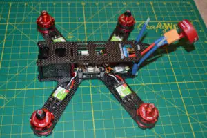
This guide on building a quadcopter will take you all the way from basic soldering to fully assembling your quadcopter. It assumes you are a complete beginner, but you do know basic electronics(negative, positive, what voltage is), and you’re familiar with the parts of a quadcopter.
It also assumes:
- You have a radio
- You have a pair of FPV goggles
- You have a charger
- You have some batteries(1300-1500mah 4S are good for beginners)
If any of this sounds unfamiliar to you, either go through the links first, or check out my guide to getting started with FPV.
I recommend going through the guide once before sitting and attempting to build it – I’ve written it so that you can follow along as you build, but it’s good to be familiar with the process before you cut up any wires.
This is not the only way to build a quadcopter – some people build in a different order, and the end result is obviously the same. Ultimately, it’s a matter of finding what is the most comfortable and fun for you.
For this build, I’ll be using:
- Generic 210 QAV-style frame
- RacerStar RS2205 2300 kv motors
- RacerStar Lite 30A ESC
- Generic Matek PDB
- Omnibus F3 flight controller
- AOMWAY FPV transmitter
- HS1177 FPV camera clone
- Foxeer RHCP antenna
- FrSky XM+ Receiver
- King Kong 5040×3 props
However, you can use any parts you wish!
Here are some posts to get up to date with the best gear:
Check out this post for some retailer recommendations to see where you can source your parts.
Tools required
- Good soldering iron(at least 50W), preferably with a thin tip(read review of my favorite iron, the TS100)
- Good quality 60/40 solder
- A set of hex drivers(M2 and M3)
- A small Phillips head screwdriver
- A pair of wire strippers or a small pair of sharp scissors
- A pair of wire cutters or a small pair of sharp scissors
- (A hobby knife will do the trick for all three tools if you don’t have them)
- 12 or 14 AWG silicone wire(one red, one black preferably, but colors don’t matter if you mark which one carries which polarity)
- A female XT-60 connector
- 15mm heat shrink tubing for ESCs
- 5 or 6mm heat shrink tubing for insulating battery lead
- 3mm heat shrink tubing for insulating any wires you may splice
- Zip ties
- Electrical tape
- Double sided tape
- Blu tac(optional, not necessary if you have soldering helping hands)
- A heat gun or a lighter for shrinking heat shrink(you can also use the barrel of your soldering iron)
Soldering for quadcopters
If this is your first time in the hobby, chances are you have never soldered before – neither did I the first time I built my copter, and I had honestly no idea how to do it correctly.
Once you get the hang of it, soldering is actually quite easy.
Most important: in order to solder well, you need to have a soldering iron with a clean tip and one that can get hot enough.
I would recommend you first try soldering some loose wires just to see how the solder reacts when you heat it and apply it to a wire before attempting to solder any components.
You also need to make sure your soldering iron tip is the right size! It will be very hard soldering small components with a thick tip, so it’s better to use a thin tip soldering iron with a slightly higher wattage(50-60W) to solder large pads as well as small joints.
With that being said, here’s how you go about it:
- Plug in the soldering iron and wait for it to heat up. You’ll know it’s ready when you can touch the soldering wire to the iron and it immediately melts
- Clean your tip on a damp sponge or some soldering wool to make sure any dirt and impurities are gone
- Add a tiny drop of solder to the tip. This is very important, because the melted solder will help in transferring the heat
- Assuming you want to solder two wires together, touch the tip of your iron(which has the dot of solder on it) to the wire, and touch the solder to the wire in a way that it’s touching both the iron and the wire. You’ll see that the solder melts and begins to flow all over the wire. Make sure you’ve coated the exposed wire on all sides – if the solder does not flow automatically, hold your iron near where you want to flow the solder and apply some more
- Flow is key here – solder tends to flow wherever there is heat, so even if you heat up one part of the wire, if more parts of the wire are hot enough, solder will flow there, too.
- Repeat this process with a second wire, so you have two wires
- Now to join the wires together, you just need to bring both exposed, soldered(tinned) wires together, and use your soldering iron(add another dot of solder to the tip if necessary) to touch one wire. As the solder on the top wire melts, it’ll heat up and cause the solder on the bottom wire to melt, too, and the solder from both wires will fuse into one gob of molten solder.
- Lift your iron up to let the solder cool and dry(one to three seconds) and you’ll have two joined wires!
You can apply this same principle to soldering wires to pads, too. Just remember – heat is key!
Safety tip: If you’re holding the wire with your hands, it can get very hot! It’s best to use a pair of soldering helping hands to hold everything in place, but if that’s not available, use something heavy to weigh the wires down so they stay in place. You can also use a pair of tweezers for gripping the wires and holding them in place to avoid burning your fingers.
Prepping the frame
When you first remove a carbon fiber frame from the packaging, it’s a good idea to wash it in soapy water with a sponge to remove any carbon fiber dust that still may be on the edges. Most high quality frames won’t have this issue, but if you are using a clone frame, it’s a really good idea to do this step. Make sure you wash all the parts – the smaller ones tend to have the most dust on them.
Do all of the scrubbing inside water, so none of the dust can become airborne.
Once you are done, you can wipe down the frame with an old towel or rag and you’ll be good to go.
As a bonus, you can apply some CA(superglue) all along the edge of the frame – or at least the arms and bottom plate – to prevent the carbon fiber from de-laminating in a crash.
Soldering the XT-60 pigtail
The next step I like to do is prepare the XT-60 pigtail. I prefer soldering a ready pigtail to the PDB instead of soldering the connector on last after building the entire frame because it’s a very fiddly job(unless you are using helping hands, in which case, do the pigtail last, as it will allow the most flexibility in positioning the connector).
First, you’ll want to measure how much wire you are going to need.
Depending on the frame you are using, the battery will be top or bottom mounted. To figure out how much wire you’ll need, place the PDB on the bottom plate of the frame on top of the mounting holes. On some frames, you can mount the pigtail so it’s sticking out of the side. On others, the pigtail will stick outside the back.
Ideally, you want enough length so that the connector just sticks out of the top plate of the frame, so that when you plug the battery in, the combined tension of the battery lead and the lead from your PDB will hold the wires in place.
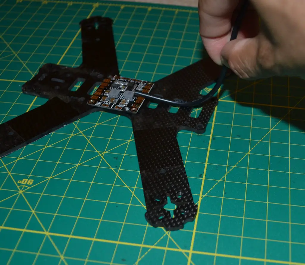
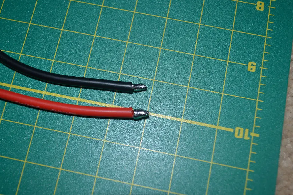
Cut the wires to that length, and strip both ends of the negative and positive wire to expose a bit(3-5 mm) of bare wire. Using your soldering iron, tin both ends of the wires with a generous gob of solder and make sure that the exposed wire is coated all around with solder.
Next up, we’ll solder the XT-60 to the wire. On the connector, you’ll see that one side is marked with a – and one side with a +. Do not screw this up!
Weigh down your XT-60 connector with a pair of pliers or clamp it in some soldering helping hands, touch your soldering iron to one of the cups and flow a good amount of solder into it. It may take a little longer for the cup to heat up enough for the solder to melt.
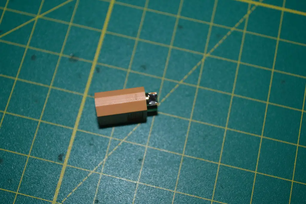
Repeat with the other cup.
Now take your positive wire(which you have already tinned), hold it on the cup in a way that the exposed, tinned part is touching the solder inside the cup, and place your soldering iron on the exposed part of the wire. The heat will flow through the solder on the wire and the solder in the cup, which will cause the solder to melt and fuse together into one gob. Remove the iron and hold the wire in place for long enough for the solder to solidify, and repeat with the other side.
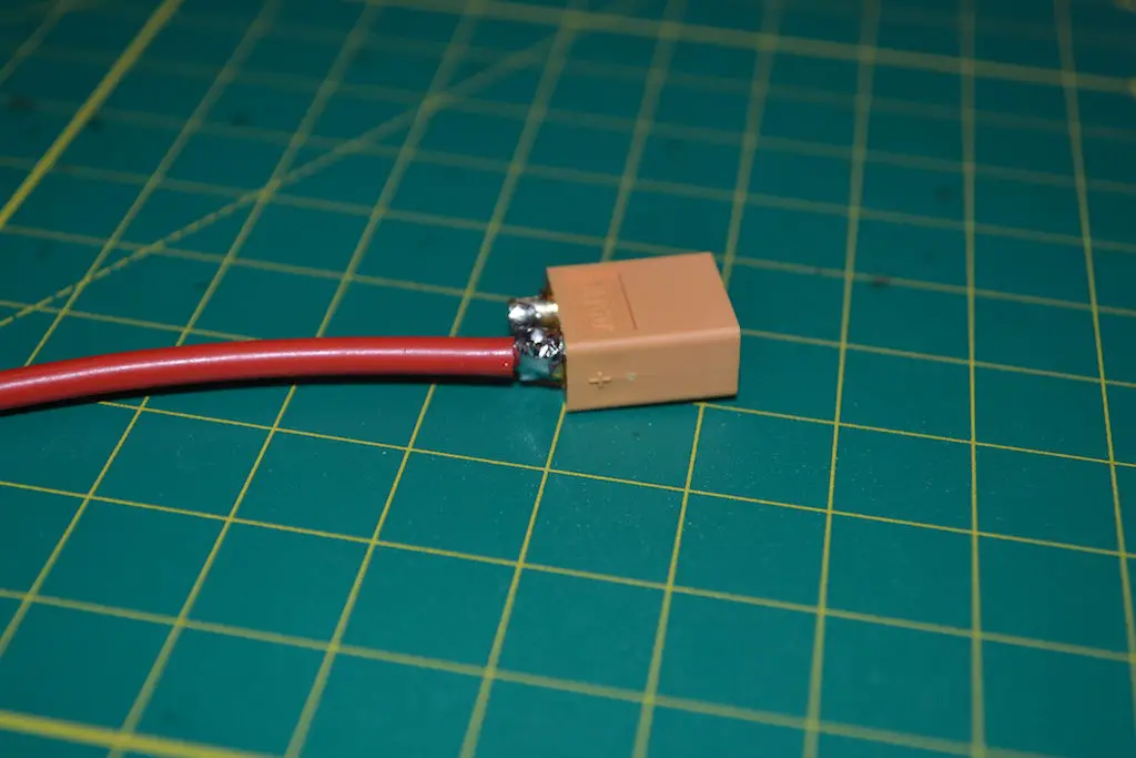
Then slide some 5mm or 6mm heat shrink up both wires and use a lighter, the barrel of your soldering iron, or a hot air gun to shrink the tubing around the exposed connector and insulate it.
To shrink the tubing correctly, first slightly shrink the top half of it, and slide it into the little crevice around the cup in the XT-60 connector. Once the tubing has slid in, shrink the rest of it for a tight, well insulated joint.
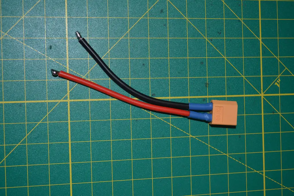
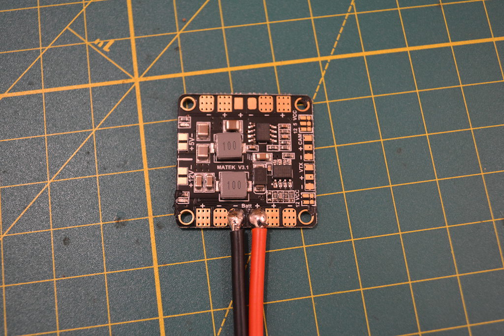
Finally, add solder to the battery pads on the PDB and solder the other end of your battery leads to them, first by stripping the wire, then tinning the wire, and finally heating up the tinned wire on top of the soldered pad. Make sure you get the polarity correct!
To do this, you’ll want to apply solder to the pad on the PDB to solder the wires onto it. Add a dot of solder to your tip, and touch the tip onto the pad. Then flow solder onto the point between the pad and the tip, and providing your iron is hot enough, solder should flow all over the pad and form a nice, shiny blob.
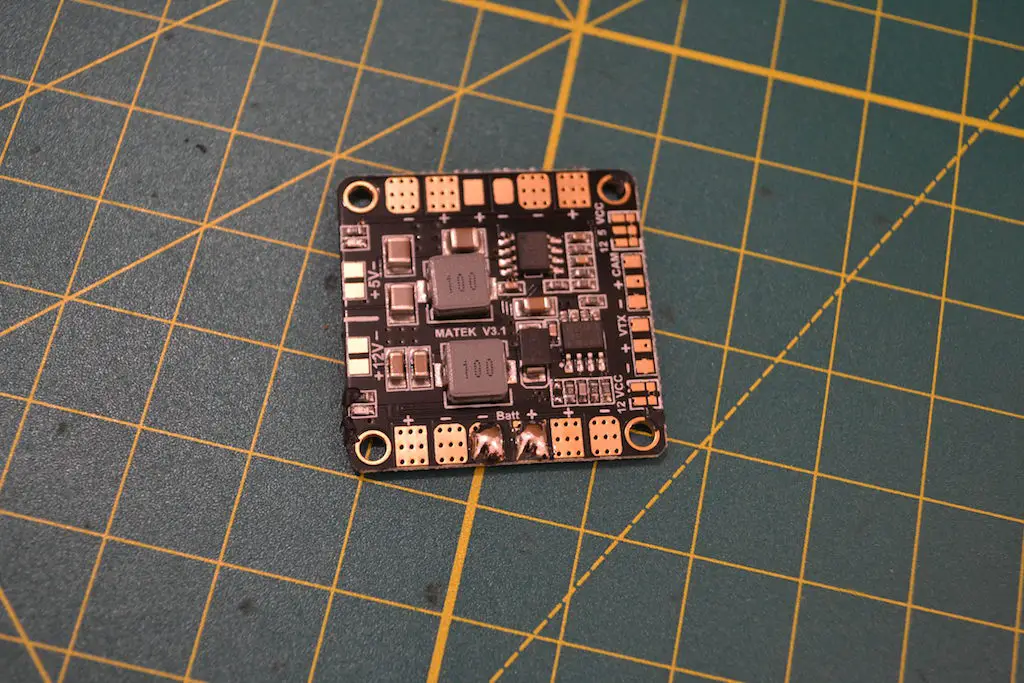
Now place your tinned wire on top of the blob, and heat the exposed, tinned wire using your iron. The solder on the wire and the solder on the pad should all flow together very nicely – remove your iron and you should have a shiny blob connecting the wire to the pad.
Soldering ESCs to the PDB
Screw one set of the little black nylon standoffs you received with your kit(hopefully) into the four holes in your frame where you mount the flight controller. Thread a screw first, and tighten a standoff on top of it. Once you have the four standoffs in, place the PDB through the screws on the standoffs.
If you want to do a flatter build, you can thread some plastic washers or nuts on the screws and place the PDB directly – this is a cleaner build, but make sure the PDB is not touching the carbon fiber at all, or else you will short circuit. Nuts will provide just enough room to insert a battery strap underneath, so if you are using a bottom mounted battery, do it this way – you may need longer screws, though.
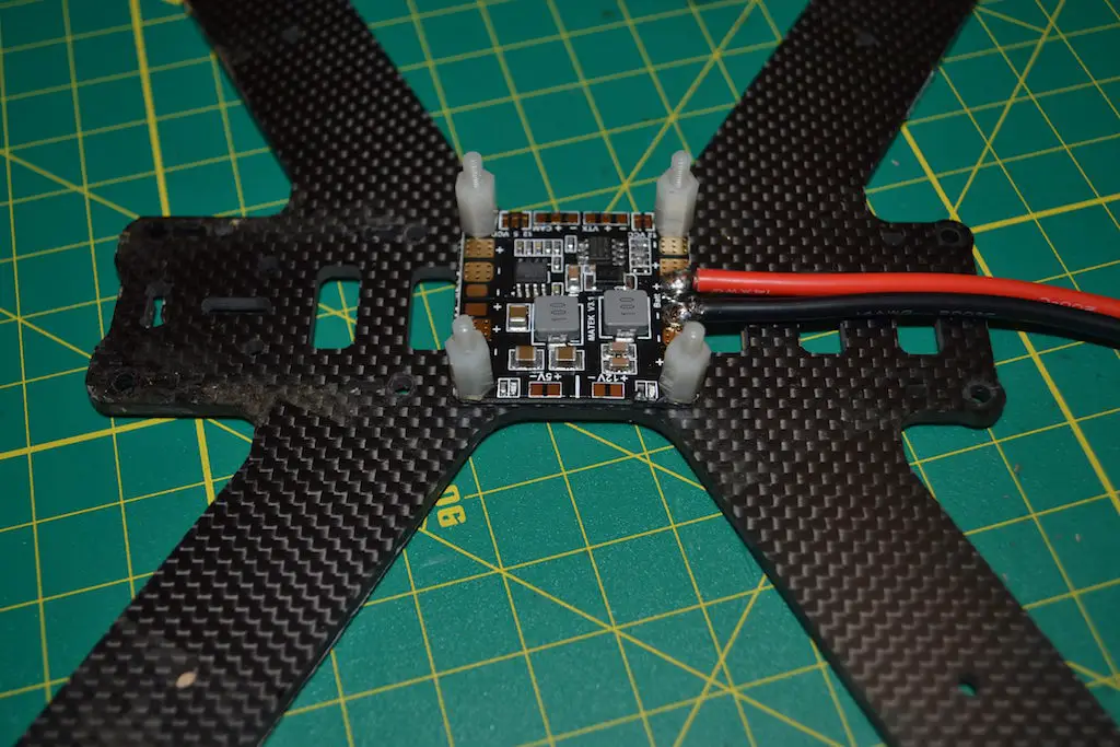
If you don’t have washers, use electrical tape or liquid electrical tape to insulate the bottom of the PDB first. This is what I have done, so my PDB is touching the carbon fiber, but it’s insulated from the bottom.
With your PDB in place, it’s time to start soldering the ESCs.
This is assuming you have a unibody frame – if your frame has separate arms, make sure you’ve assembled the arms to the bottom plate before moving ahead.
I’ll talk you through placing and soldering the leads for one arm – you just need to repeat this process for the other three arms.
First, you’ll have to prep your ESC. If your ESC already has three exposed pads on one end for soldering motor wires, you can skip this step. Otherwise, you’ll want to remove the heat shrink and desolder the three wires that connect to motors.
This is an entirely optional step and you could just solder the motor lead to the lead sticking out of the ESC, but directly soldering motors to the pads on the ESC is always a much cleaner build.
To desolder the wires, apply a dot of solder to your iron, and touch the iron to the blob of solder holding the wire onto the esc. It should heat up and melt nearly instantly, and you can just lift it off. Repeat for the other two wires.
Now, using a bit of blu tac or double sided tape, stick the ESC about halfway-two thirds away from the motor mount holes on the arm, with the motor side facing the motor holes and the power wires towards the body of the copter.
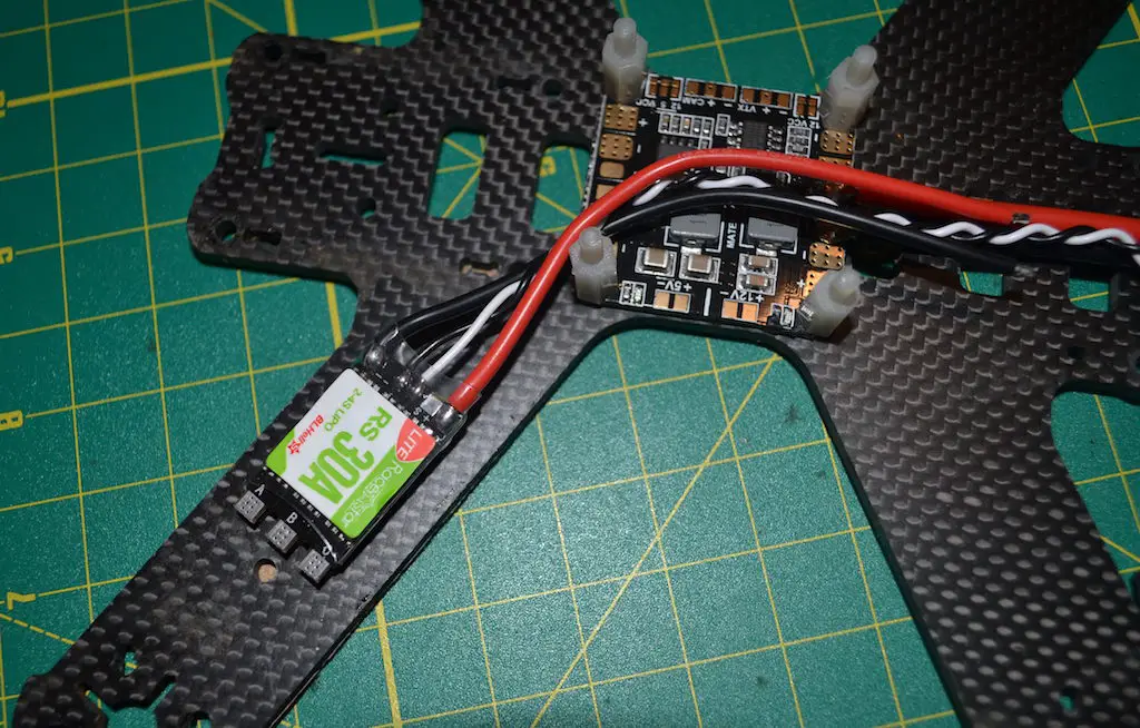
Run the two leads to their corresponding pads on the PDB(red to + marked pads and black to – marked pads). Your PDB may have the pads arranged in corners for easy soldering. The ESC pads are usually fairly large. To make building easier, just run the wires to the closest two pads, but if any standoff/camera plate holes are in the way, be sure to route them around those so they don’t get in the way.
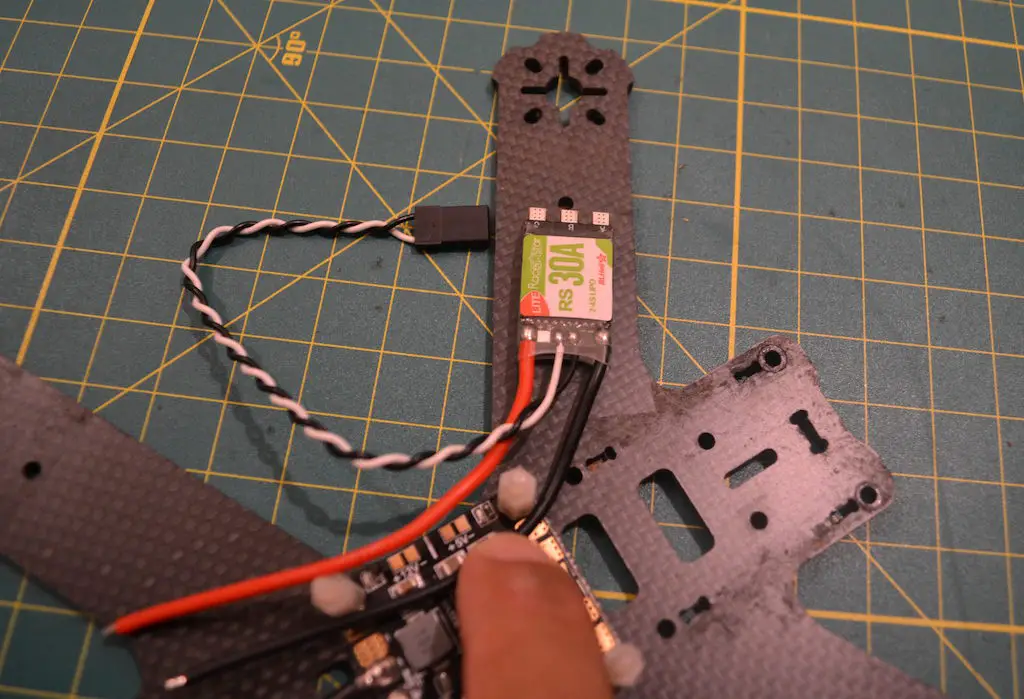
Cut off any excess wire that goes beyond what you need to solder to the pad, and strip away 2-3 mm of the insulation from both wires.
Using your soldering iron, tin the exposed wires.
Tin the corresponding pads, and solder the wires to the pads the way we did above. Make sure you get polarity correct!
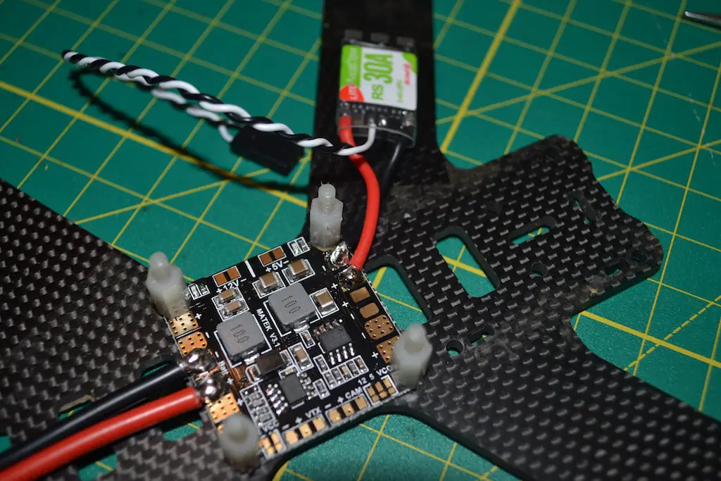
If you had to remove the heat shrink from the ESC to remove (I didn’t), cut some 15-20mm heat shrink to the size of your ESC and place it over the ESC, a little bit further away from the motor pads. Don’t shrink it just yet – this will be the last step.
At this point, you should have an ESC with the negative and positive wires soldered to their corresponding pads on the PDB. The black and white signal wires(which would have a connector at the end) are still loose – we’ll get to these later.
Repeat these steps for the remaining three ESCs.
Once you’re done soldering, take a multimeter and check for any short circuits. If you don’t have a multimeter, plug in your lipo to see what’s up!
The lipo method is not ideal, of course, since a short will result in magic smoke.

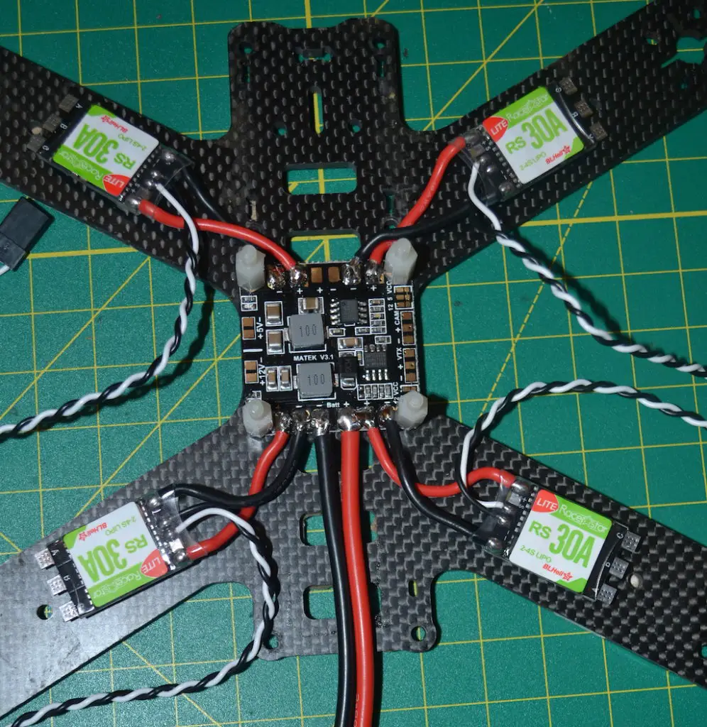
Soldering power from the PDB to the FC
This part is a little tricky, so READ CAREFULLY before you do anything 🙂
You’ll have to consult the manual for the FC you are using to check if the flight controller takes in 5V or raw lipo voltage. If you are using the same board as I am(an Omnibus F3), you can follow along directly.
If your flight controller takes in 5V, then you’ll have to solder a power and ground lead from 5V pads on your PDB(it will be marked) to any power and ground holes(pads) on your flight controller. Usually, these will be in line with the motor outputs – so if your flight controller has motor outputs for 1-6 or 8 motors, you can solder the power and ground lead to any of the holes for motors 5-6/8.
Make sure you check correctly which kind of voltage your flight controller can take! If you screw this up, you’ll see magic smoke.
On most flight controllers, the ground pad would be the one towards the outside edge of the board, and the one immediately next to it to the inside would be for power.
If your flight controller is capable of taking in direct lipo voltage, it will say so in the manual or product information page, and you’ll see there is a specific pad pair to solder the power and ground leads to.
In the Omnibus F3, you can see in the diagram below which two holes those are.
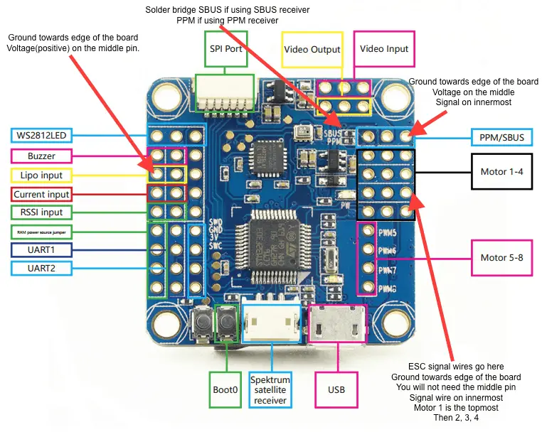
On many PDBs, you’ll find one set of unmarked, smaller copper pads – these are usually raw lipo voltage, and you can solder the leads from there to the flight controller. If you can’t find these pads on your PDB, just use the battery power and ground pads or the pads for any of the ESCs – this wire will be much thinner and the solder will easy melt and fuse with the solder on the much thicker ESC/battery leads.
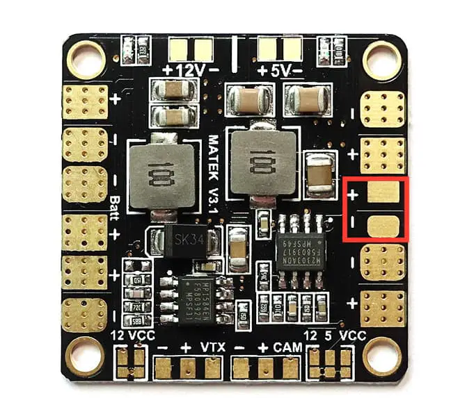
For a clean build, prop up the flight controller at a 90 or greater degree angle to the PDB. Solder one end of your two leads(you’ll need a bit of spare wire) to the PDB, and strip away a small amount of insulation from the other end. Twist the exposed wire to make sure there are no loose threads, and push the wire through the back of the corresponding hole to the front of the board.
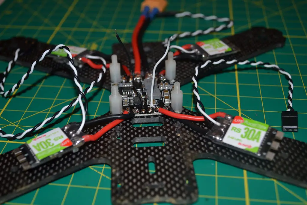
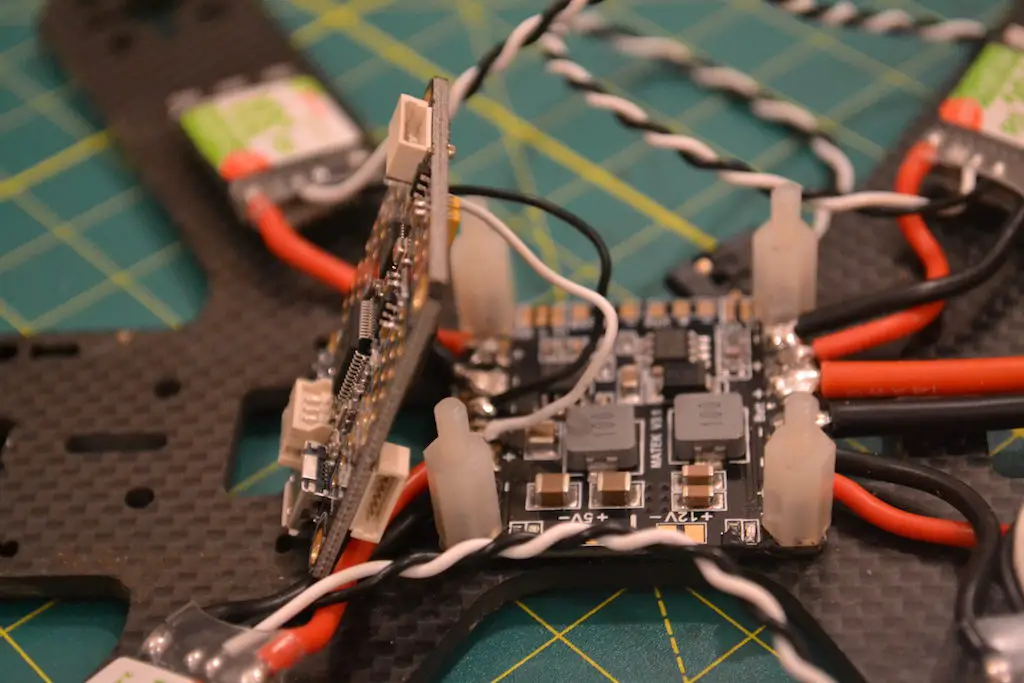
Then just apply your soldering iron and a tiny bit of solder to the pad and exposed wire, and you’ll see the solder fuse very nicely with the copper pad around the hole and the wire itself. If there is any excess wire sticking out above the solder joint, trim it with a pair of fine scissors. You don’t want any extra wire anywhere!
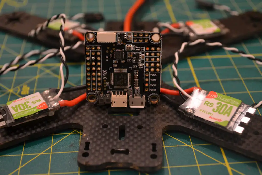
Soldering power and connections for FPV gear
Before you start this section, remember to check carefully what kind of voltage your FPV camera and video transmitter can accept! Most newer ones can take in lipo voltage from 2S-6S, so you don’t need to worry, but it’s better to be safe than sorry.
As always, there are a couple of ways to go about this.
You could either solder everything to your Omnibus FC – or you could draw the power and ground from the PDB and just connect the video wires to the FC.
If you are using an older FC, you’ll have to do everything from the PDB, of course.
I’m going to draw power and ground from the PDB, and only solder the video wires to the FC.
Take the connector that came with your camera, and hold the connector roughly where the camera will sit. If you want, plug it into the camera and position the camera with the angle you want. This is just to measure how much wire you are going to need.
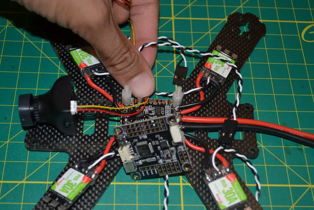
Run the red and black wire to the solder pads you are going to solder them to. Keep about 1-2 cm of flex in the wire, just to be safe, and trim the rest of those two wires off. Leave the yellow video wire as is for now. If your camera has two more audio wires and you wish to use audio, leave those too, for now.
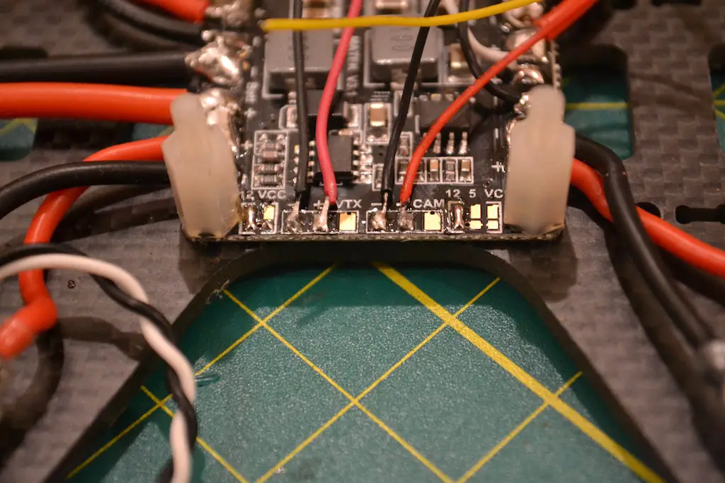
Many PDBs(such as the one I am using) have dedicated solder pads for the FPV equipment. You can use those – and it’s actually better to use those, since you’ll get filtered power immune from any voltage spikes that may mess with your video signal.
Sometimes, in such a case, there will be a set of tiny pads nearby marked with different voltages – you’ll have to bridge the pads for the voltage you want – stick to 12V, since 99% of FPV equipment will run perfectly with 12V – unless you are using a Runcam Split, which can only take 5V!
To bridge the pads, apply solder to one pad so you get a nice bubble, and simply heat the nearby pad you want to bridge – the solder should flow automatically.
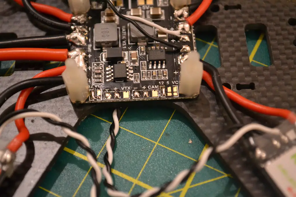
Once you have bridged the pads, solder the ground and power to their respective pads.
We’ll be repeating the process for the video transmitter. Take the connector, and run it to roughly where you are going to mount your transmitter. The easiest place to mount it is underneath the top plate, so just hold it about 3-4 cm above the bottom plate a little bit behind center(for a long body frame).
Like before, run the power and ground wire to the other set of solder pads on your PDB, and with 1-2 cm of flex in the wire, trim the rest of the red and black off. Leave the video, and audio if you are using be for now.
Bridge the voltage pads like you did earlier, and solder the wires to the corresponding pads.
If you are using an Omnibus FC and want to use the Betaflight OSD, you’ll have to solder the camera video wire and video transmitter video wire to the corresponding pads on the flight controller. Refer to the diagram we looked at above to see which pads to solder to – remember to solder them correctly, since one is marked VIN(camera) and one is marked VOUT(transmitter).
You can either solder them by threading the wire through the hole and heating the pad like we did before, or you can add a blob of solder to the pad(it’ll cover the hole up), and just solder the wire to the blob.
If your FC is still upright when you are soldering, remember to keep enough flex in the wire as you trim it so that there is room for it to run even after you mount the FC flat on the standoffs!
If you aren’t using the Omnibus or don’t wish to use the OSD, you can
- either solder the two video wires to their corresponding pads VIN and VOUT to the PDB
- solder the two video wires together directly – but if you do so, remember to put a piece of thin(2mm or 3mm) heatshrink on the wire before you solder them together! Once they’re soldered, just shrink the heatshrink around the joint to insulate!
If you are using audio, just solder the camera audio wires to the corresponding audio wires on your video transmitter – it’s as easy as that. Remember to trim the wires to length(video and audio) so you have a neat build.
At this point, you’ll have two connectors sticking out of your PDB – one for your camera and one for your video transmitter – we’ll be attaching those as the last step.
Soldering your receiver to the FC
This part of the build covers using an SBUS receiver with your miniquad. If you are using a Spektrum receiver, I’ll add a few notes at the end of this section that will help you.
If you are using a PWM or PPM receiver, don’t. Invest $10-12 in a little SBUS receiver – it’s faster, smaller, and lighter – what’s not to like?
I will be using a FrSky XM+ receiver here with my Omnibus F3. From the wiring diagram we saw above, you’ll see that there are three holes/pads for the receiver – your receiver will get 5V of power from the flight controller, so one hole is for the signal, one is for power, and one is for ground.
Next to the receiver pads, there are two tiny sets of solder pads, one labeled SBUS and one labeled PPM. Since we’re using an SBUS receiver, we’ll be bridging the two pads labeled SBUS. Add solder to one pad by heating it up and flowing the wire, then just heat up the adjacent pad – since the pads are so close, the solder should automatically flow there.

Solder one lead to each of the pads on the XM+ receiver(consult the manual to see which pad is which, and make sure the receiver is the right side up so you don’t solder backwards!), and solder the other end to the corresponding pads on the flight controller.
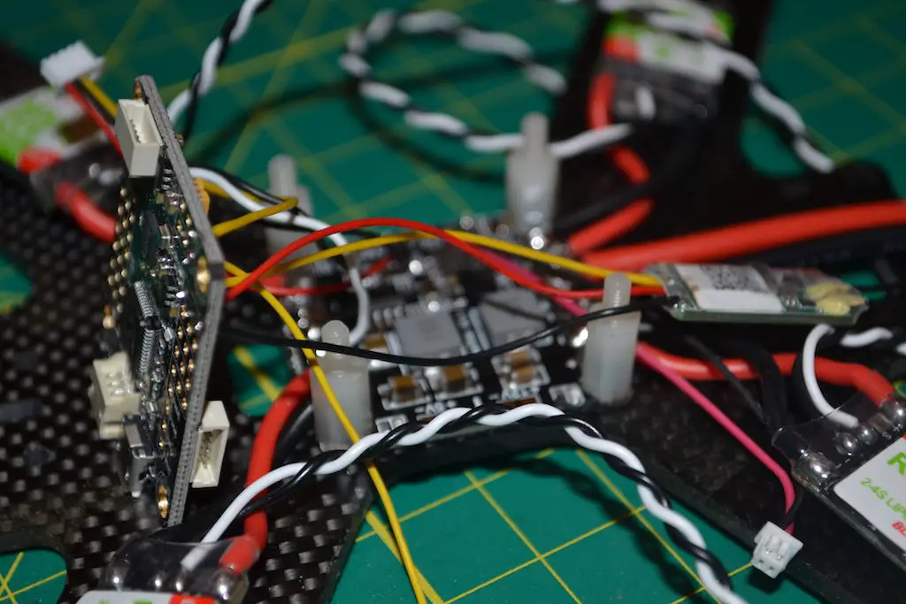
For other flight controllers, you will have to see the wiring diagram to see where the pads are.
If you’re using the XM+, shrink the heatshrink around it once you are done.
Soldering your ESCs to the FC
There is an easy way to do this, and a more tedious way.
For a neat looking build, you can thread the ESC signal and ground wires between the PDB and the FC and through the holes from the bottom, like we saw before..
You’d have to do this by positioning your FC sideways, threading the wires one by one, and soldering them. It’s safer to have a little flex in the wires here – if you cut the wires too short, you won’t be able to put the FC flat on the standoffs – and it can be a little deceptive when the FC is upright how long the wires actually need to be.
If you have some means of holding the FC in place as you do this, It’ll make your life easier. If and when you need to replace an ESC, just desolder the wires from the ESC and resolder to your new ESC.
The easy way to do it is:
By now, all necessary connections to the flight controller are complete, besides the ESCs, of course.
You can mount the flight controller on to the standoffs and even use the nuts to fix it in place.
On your flight controller, there will be series of 3 holes marked M1-M4, or PWM1-PWM4 – this depends on the FC you are using, so it’s best to consult the diagram first.
In this build, I am using an Omnibus, so this is what the diagram looks like:

We’re going to solder the signal and ground(optional, but recommended) wires to the corresponding pad on the flight controller.
I prefer direct soldering because it is stronger and results in a cleaner build – you could use pins, but you’d have to have soldered them on before mounting the flight controller.
Refer the diagram below to see which order the ESCs are supposed to be numbered in:
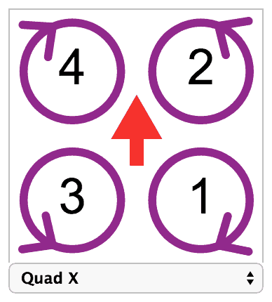
To solder the ESC signal and ground wires, run the wire to the solder pad to measure how much wire you’ll need – when cutting the wire, make sure you cut the signal wire and the ground wire to their corresponding lengths, because the pads are a little further apart! It’s also a good idea to cut the wires just a little longer because you’ll have to route them a little bit to accommodate the wires from the remaining ESCs.
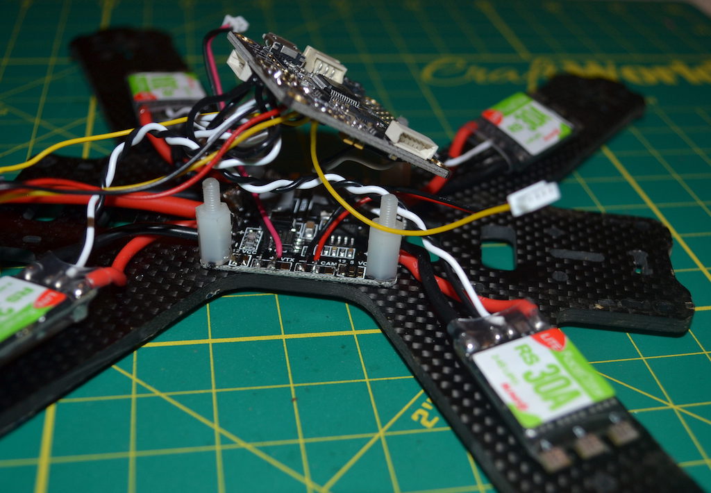
Note: This is what a finished product would look like(I’ve threaded the wires from the bottom):
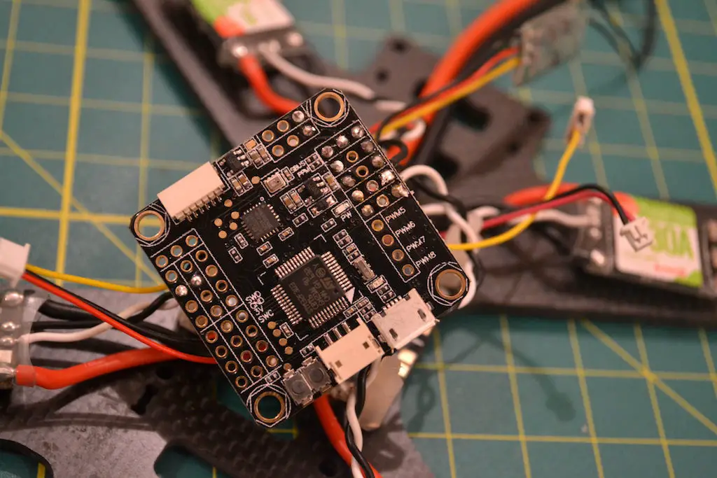
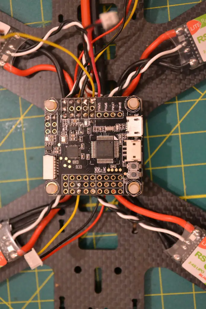
After you cut the wire, strip away a tiny bit of insulation, and tin the exposed wire. Apply solder to the pad you want to solder to so a little bubble forms, and melt the exposed, tinned wire onto the solder pad. Do this for the ground and signal wires.
The signal pads will all be in one row, as will the ground pads – make sure you refer to the diagram to see which is which!
Repeat this process for the remaining ESCs one by one, cutting just a little longer wire than needed to route them comfortably together.
Note: Have a look at this picture of a much older build where the ESC wires were routed from the top of the board and soldered on to the holes.
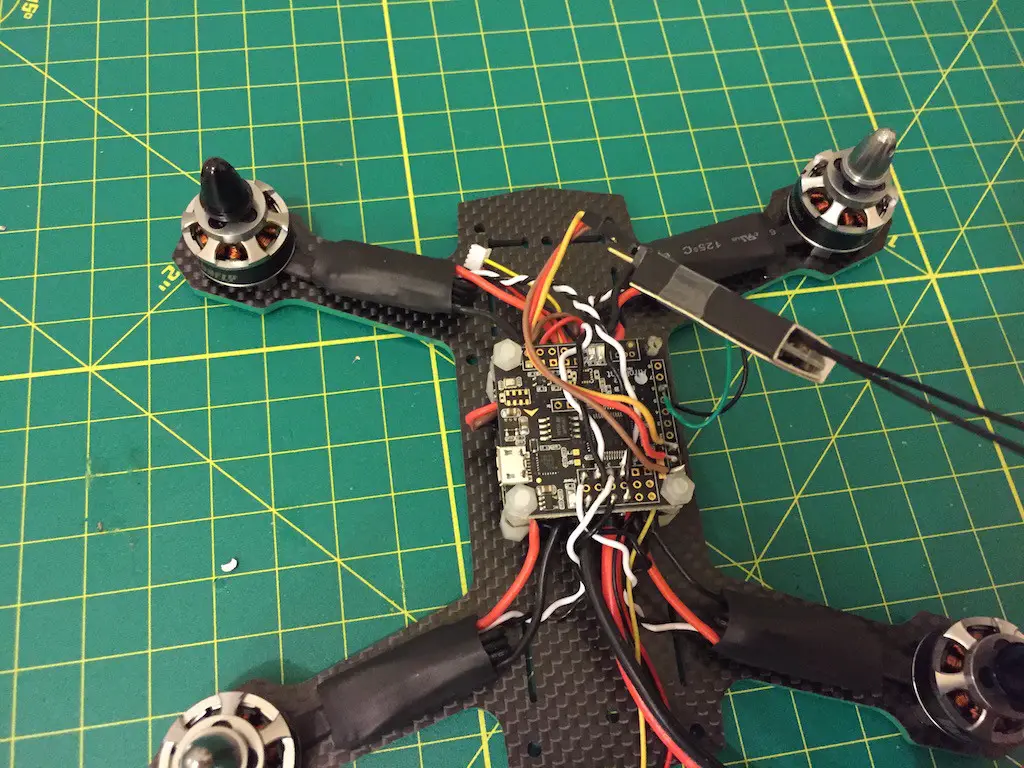
As the last step, place the flight controller flat on the standoffs, and secure it with nylon nuts. Just make a note of which direction the arrow on the flight controller is facing – if it is not forward, we can fix it in the software configuration later – it’s actually easier to mount it at a 90 or 270 degree angle because that way the USB port is easily accessible.
Mounting motors on the arms
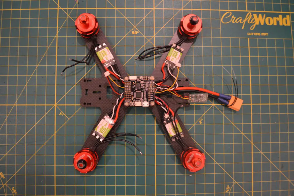
At this point, the majority of the work is done so it’s time to mount motors! Your set of motors may be of two types:
- All CW locknuts
- 2 CW and 2 CCW locknuts(what I’ve got for this build)
Here’s where it gets trippy. If you are using all CW locknuts, you can ignore this step. If you are using 2 sets of different motors, mount the CCW locknut motors on the arms where the motors will spin CW, and mount the CW locknut motors on the arms where the motors will spin CCW.
This is because the nuts have to turn in the opposite direction as the motors, so they don’t fly off because of inertia.
A neat way to check which is which is to loosen the nut all the way, and grip the nut between your thumb and forefinger on top of the motor shaft. Then turn the motor with your other hand in the direction it’s supposed to spin(clockwise or counterclockwise). If the nut tightens down as you spin the motor, it’s the right one.
To mount motors, get the screws out of the packet – you’ll need to eyeball it to see if the longer screws are suitable or the shorter ones. For 4mm frames, you’ll usually need the longer ones.
Squeeze out a few drops of blue threadlocker onto a piece of paper or some plastic packaging you have leftover. Hold the motor on the arm(make sure the wires coming out of the motor are as straight down the arm as possible) and align the holes in the motor with the holes in the arm. Take one screw, dip the bottom in the threadlocker, and screw it into the motor – you don’t need to screw it in all the way, just enough that the threads have caught the motor and it’s attached to the arm, but still has some play in it.
Use this play to align the holes again, dip a second screw in threadlocker, and screw it in the hole opposite the one you put the first screw in.
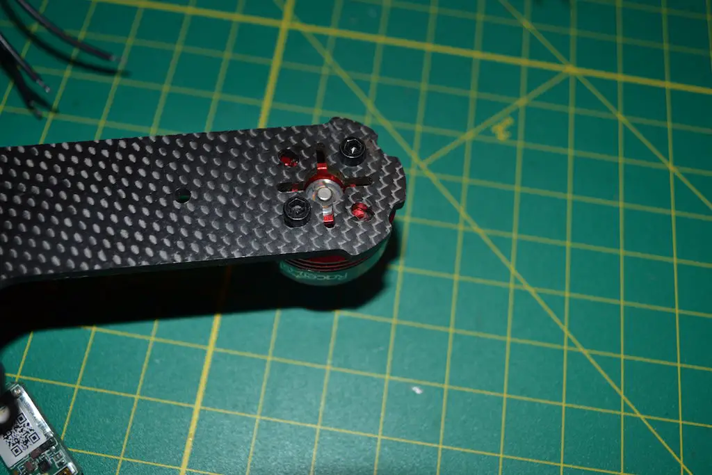
You only need two screws to hold a motor in place – if you want, do all four, but it is not necessary.
Once both screws have caught the threads, tighten them in all the way.
Repeat this process for the remaining arms, and if you’re using motors with differing locknuts, remember to use the correct one on each arm. For reference, here is the diagram again:

Soldering motors to ESCs
With the motors screwed in, it’s time to cut the motor wires to length and solder them on to the ESCs.
Hopefully you’ve got the fresh heatshrink around your ESC (which has not been shrunk yet), so just push it back as far away from the motor solder pads on the ESC.
It’s a good idea to apply some fresh solder to the pads on the ESC for a quicker and stronger bond, so heat up your iron, add a dot of solder to it, and flow some solder on to each pad. Just heat up the pad so the existing solder melts, and flow a little bit of fresh solder onto each pad using your solder wire.
You should have 3 shiny blobs of solder.
Now grab the motor wires and measure them to the solder pads, and cut off the extra wire. Expose about 2mm of wire from the insulation on each of the three wires, and tin the wires.
Take each individual wire and hold the exposed, tinned part on the solder pad on the ESC. Apply heat using your iron, and the wire should fuse together nicely with the pad. Repeat for the other three pads. Just solder all the wires to the pad directly corresponding to it – you don’t need to cross any wires anywhere.
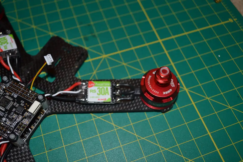
Repeat for the other three motors.
Now you can move the heatshrink back over so it covers the entire ESC, but don’t shrink it just yet. We’ll do that last, once we know that everything is working A OK.
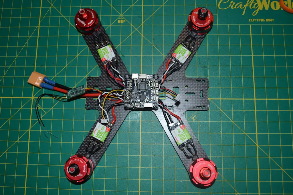
I used double sided tape on an already insulated ESC – so these ESCs aren’t going anywhere, and I don’t have to secure them any further.
If you are heat shrinking the ESCS again, then once you’re done with the build and you’ve shrunk the heat shrink down(last step, after you gone through this entire tutorial), use a zip tie or electrical tape to hold the ESC down.
Adding FPV transmitter and camera and assembling the frame
All of our soldering work is done! Phew!
Up until now, we only had the bottom part of the frame assembled – if you were using a frame with swappable arms – or were just working with the bottom plate if using a unibody design.
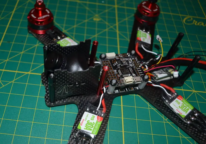
Now, grab the standoffs that came with the frame and screw them all onto the bottom plate. You may need to play a little with the ESC wires – don’t worry about moving them around, as the solder joint will hold. Just don’t pinch the wires between the carbon and the standoffs.
You may notice that our receiver is still dangling in the air – grab a bit of double sided tape and stick it on the bottom plate wherever you can find room! Just make sure to keep the antennas accessible, as we’re going to be mounting them last.
With the standoffs all in, take the side plates(camera plates) that came with your frame, make sure they are the right side up and facing the same way – check by inserting them into the slots on the frame to see if the holes align.
Using the screws that came with your FPV camera, screw the camera onto the plates through the holes in the plates. Don’t tighten all the way just yet – you may need to make adjustments, so you can do that last.
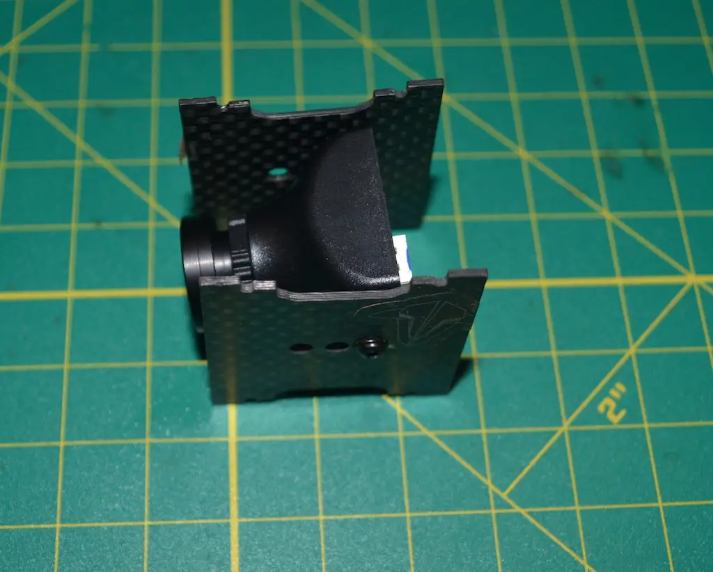
Plug the connector we soldered in earlier into the camera, and insert the plates into the slots on the frame. You may have to play a little with the plates and ESC wires to get them in.
Now grab your video transmitter, and screw on the antenna. Plug the second connector into your video transmitter, and grab your top plate.
Use a bit of double sided tape or velcro to stick the transmitter on the underside of the top plate. This is just for basic adhesion – we’ll use zip ties to reinforce it. For reference, place the transmitter around the slots on the top plate that correspond roughly to zip tie holes for a transmitter and antenna.
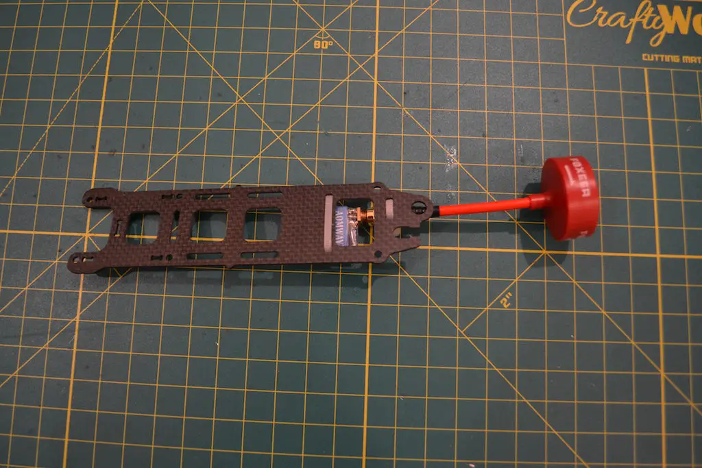
Take some zip ties, run them through the slots, and tighten them down, securing the transmitter and antenna to the top plate.
Not all frames have these slots, but most do.
Tip: If you are top mounting the battery, secure the zip tie so the locking mechanism is below the plate, this way the sharp cut off zip tie will not dig into your battery.
I like to mount the FPV antenna in such a way that the connector is protected inside the frame, and only the rest of the antenna is poking out.
Related: How to mount your FPV antenna
On some frames, there is a hole for threading a connector through, then screwing the connector down, and screwing the antenna on top of that – you could do this, but in my earlier experiences, the screw would get loose thanks to vibrations and an upside down landing or crash usually broke the connector.
Before you screw on the top plate, though…
Mounting your antennas
Finally, we come to the antennas. The most common way to mount them is using the bunny ears method. Mr Steele improved this method – which greatly reduced the number of broken zip ties – and that’s the method I prefer to use.
You’ll need some 5 or 6 mm heatshrink, and some 3 or 4mm heatshrink as well as two zipties.
First, cut some 5/6 mm heatshrink to 3cm. Place the heatshrink over the back standoffs. Now run a ziptie through the heatshrink so the locking part is sticking out of the bottom, and the tip extends above the frame.
Now grab one of the two antenna leads, and run it from the bottom of the heatshrink out the top, along the zip tie.
Cut a bit of 3 or 4mm heatshrink to length, and thread it over the zip tie from the top, taking the antenna in with it. Now you should have the heat shrink tubing cover both the zip tie and the antenna.
Push the heat shrink tubing down a little so the smaller tubing goes inside the larger tubing around the standoff.
When you shrink it down, the larger tubing will hold the zip tie, the antenna, and the smaller tubing all in place.
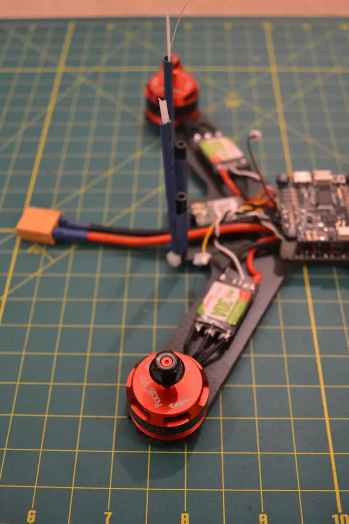
Repeat for the other antenna, if your receiver has one.
Now that everything is connected, all that’s left to do is place the top plate on the standoffs and screw them all in!
Battery mounting
There are two good ways to mount your batteries: either using velcro or using some foam.
- Velcro: Stick some velcro on all of your batteries, and cut a similar sized strip and stick it on the quadcopter wherever you’re planning on mounting the battery. If you aren’t going to use an HD cam, try and keep the battery as close to the center of your quadcopter as possible. If you are going to use an HD cam(Runcam Split does not count!) and top-mounting the battery, it’ll be right behind the camera, and will probably take up the remaining space on the top plate.
- Foam: Cut a strip of foam(2mm – 3mm thick) and stick it wherever you plan on mounting the battery, as described above. When you tighten down the battery using a battery strap, there is a lot of friction between the battery and the foam and it won’t move.
Changing motor rotation with BLHeli_S
With all of the building complete, we just need to check motor rotation to make sure all four of the motors are spinning in the correct direction.
Plug in your lipo and plug in the board to your computer with a USB cable.
Go into the Betaflight Configurator, connect, then in the Motors tab, check the warning box for motor testing(make sure props are off).
Gently bump up the slider for motor 1 until it starts spinning, and feel the bell from the side with your finger to see which direction it’s spinning in. It should be spinning clockwise. If not, make a note. Move down the slider.
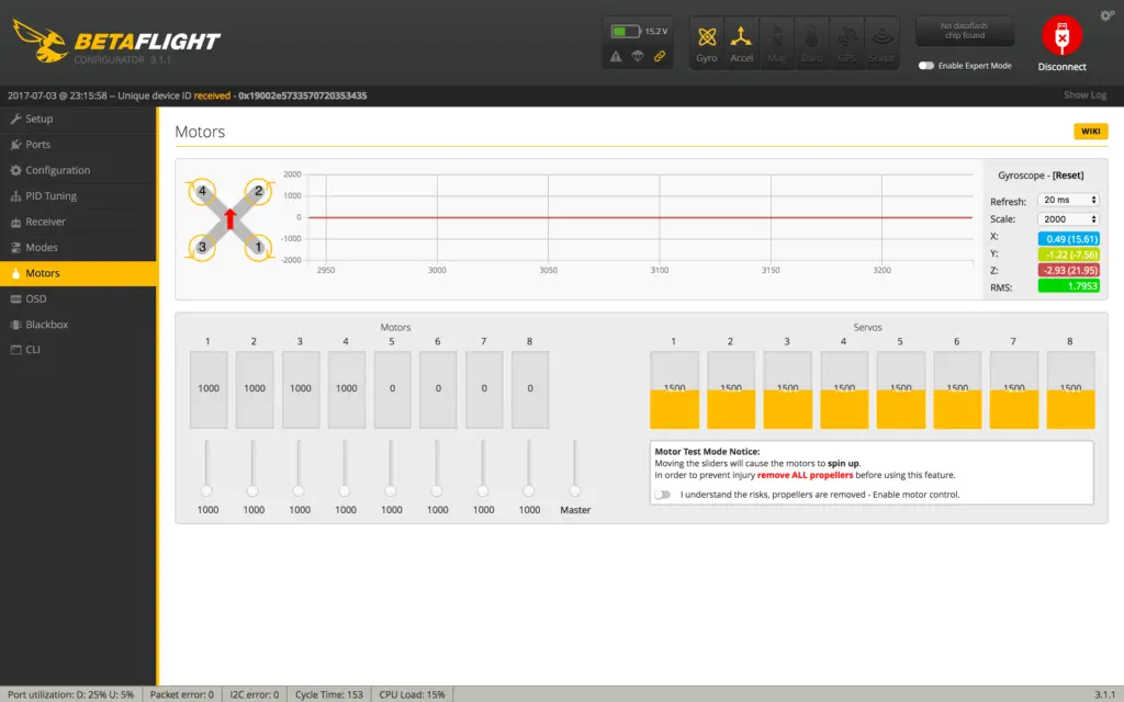
Now do the same with motor 2 or 3 – these should be spinning counter clockwise. Typically, it’ll be spinning the same way motor 1 was, since they are all wired to the ESC in the same way.
Make a note of which way the motor was spinning, and disconnect BetaFlight Configurator.
Now, download the BLHeli Configurator app from the Chrome Webstore, and open it. Click “Read Setup”(Your lipo must be plugged in).

Here, you can update your firmware by clicking “Flash all” at the bottom, and selecting the latest firmware version. The ESC type is usually detected automatically.
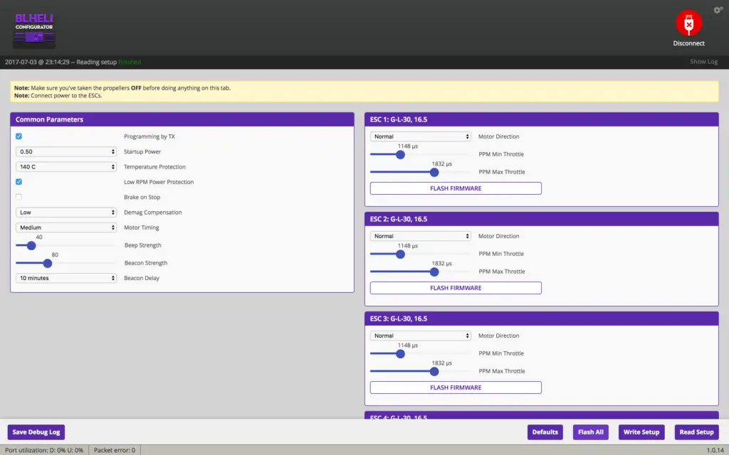
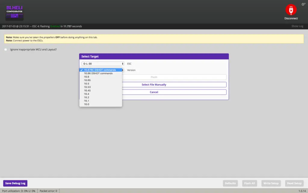
Now, provided all your motors were spinning in one direction:
- If motor 1 was spinning correctly, then you need to “Reverse” the direction for motors 2 and 3
- If motor 1 was spinning incorrectly, then you need to “Reverse” the direction for motors 1 and 4
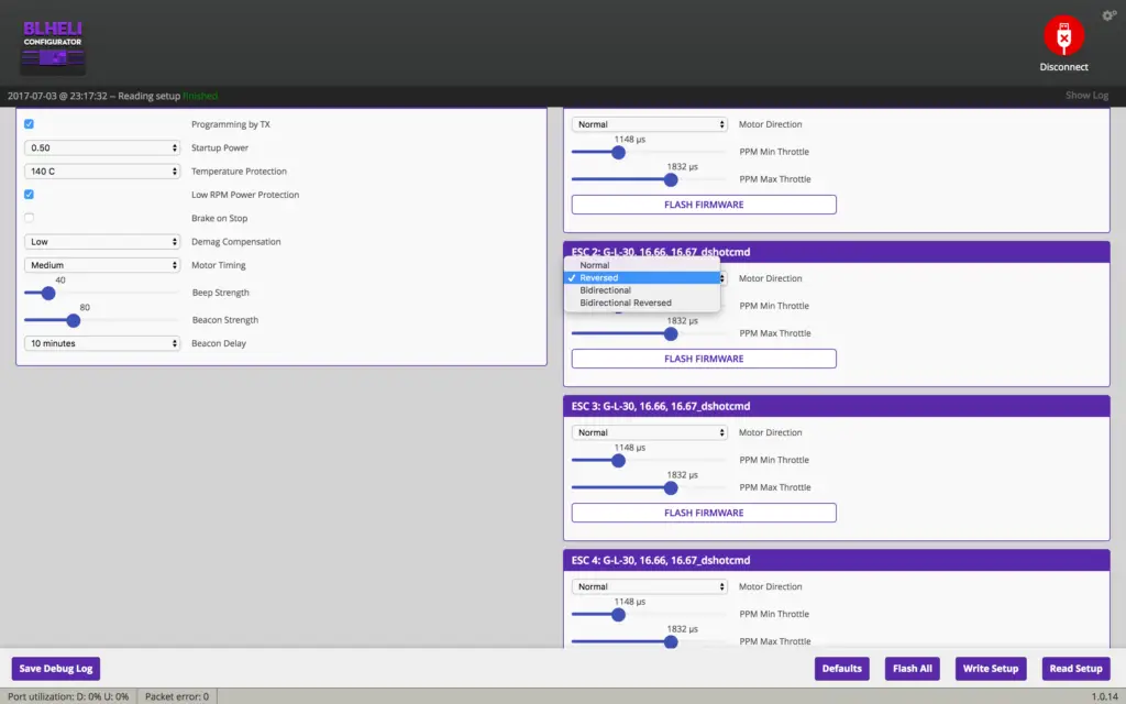
That’s it, you’re done! Shrink down your ESC heat shrink, secure them to the arms, and ogle your beautiful creation!
What next
Finally, you’ll want to head over to the BetaFlight configurator and set up the software.
I’ve written a detailed guide which you can see here.
Mounting propellers is easy – propellers marked “R” go on clockwise spinning motors, unmarked or “L” marked propellers go on the counter-clockwise spinning motors.
More help
For more build inspiration and help, these two videos from Rotor Riot are very helpful:
Hi! I made my own drone a little differently but I have the a similar FC. (It still hasn’t gotten off the ground.) One day when I was trying to take off a wire came lose and smoke started rising from my drone. I immediately unplugged battery and discovered that the ground wire i think (this symbol was above it (-)) to the transmitter came loose. Now only get a few beeping noises when I plug in the battery and the motors wont spin when throttle is forward. I was wondering what I can do. I really would like help because I spent hours on this and a good $300 thanks.
~Luke
Hi Luke,
Sorry for the long delay in getting back to you! By transmitter, do you mean video transmitter?
You’ll need to use the process of elimination to see what component actually went bad.
1) You said your motors spin up in Betaflight, so it seems your motors and ESCs are okay.
2) Do you get any video from your FPV camera? If not, then your transmitter is gone.
3) When you move the sticks on your transmitter, do the corresponding inputs move in the “Receiver” tab in betaflight?
4) You may need a new FC as the hardware is a little delicate and even a small short can cause a lot of stuff to go wrong.
Hope this helps!
also in betta flight I can get the motors to spin through master controller.
Hi Luke,
If the ground came loose it seems likely that your battery may have shorted out. Lithium batteries that have shorted out are unfortunately irrecoverable. I would recommend that you use a voltmeter to check the voltage on the battery. If it is significantly lower than the voltage it is intended to operate at, purchase a new battery and try with that.
Alternatively, grab a couple of double AA batteries (1.5 volts each). Find out how many you need to get the same voltage as the Lithium Ion (6V/1.5V = 4) and connect them head to tail. Connect this arrangement of batteries where the Li battery would normally go. I would recommend electrical tape to connect the batteries head to tail.
If this makes it work, get a new Lithium Ion. If this has no effect, something else is wrong. Send me an email at https://1ty.me/cRa6L (single-use link to prevent my email making it to the web).