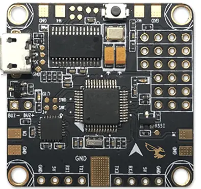
The Betaflight F3 flight controller was developed by FPV Model in conjunction with Boris B., the brains behind Betaflight. The really unique thing about the Betaflight F3 board is that it is designed specifically to be able to use all of Betaflight’s awesome features.

Let’s get this Betaflight F3 review started!
Feature overview
For miniquads, this board is just awesome. For micro quads(that support 30 x 30 mounting) it’s a dream come true.
- Built in PDB and 5V BEC
- Built in OSD support
- Built in current sensor that can handle up to 100A continuous and 160A burst
- SD Card slot for blackbox recording
- 3 UARTs
- Boot button for easy firmware flashing/recovery
- Very neat wiring
- USB port facing a convenient direction(finally!)
- SBUS support(no PWM)
- Weight: 8.6 grams
Board design
The board comes in a little plastic box packed in white foam, and includes a servo cable you can use for the receiver.
The board itself is very solid to the feel, and you actually have to use both sides of the board in your build. One side of the board has pads for running ESC power wires to, and the other side of the board has pads for the ESC signals and holes for everything else.
The main battery power leads go on the top and bottom, an interesting design choice. The positive wire gets soldered to the bottom, and the negative wire gets soldered to the top.
Now because the ESC power pads are all at the bottom of the board, soldering it is a little tricky!
Note: If you decide to follow this post as a guide, READ THROUGH the entire post before you start soldering and mounting away.
How to solder ESC leads to the Betaflight F3 board
There are a couple of ways you can do this:
- Desolder the leads from your ESCs, then solder them all at full length to your flight controller. Then, flip the board right-side-up, mount it in the correct direction, and place the ESCs on the arms. Finally, trim and solder the leads to their respective ESCs.
- On the flip side(pun intended) you can first mount the FC right-side-up, and place the ESCs on the arms. Next, run the ESC wires to where the pads would be on the underside, and trim them to length. Finally, flip the board upside down and solder. Note that this method will only work properly on a perfectly symmetrical frame. If your frame is not completely symmetrical, you’ll have to juggle the orientations in your head.
Honestly, method one is easier.
Once the power leads have been soldered on, the signal wires are very easy – the pads are at the very edges of the board, so with the board in the correct orientation, just trim the signal wires and ground wires to length and solder away.
Overview of soldering to the board
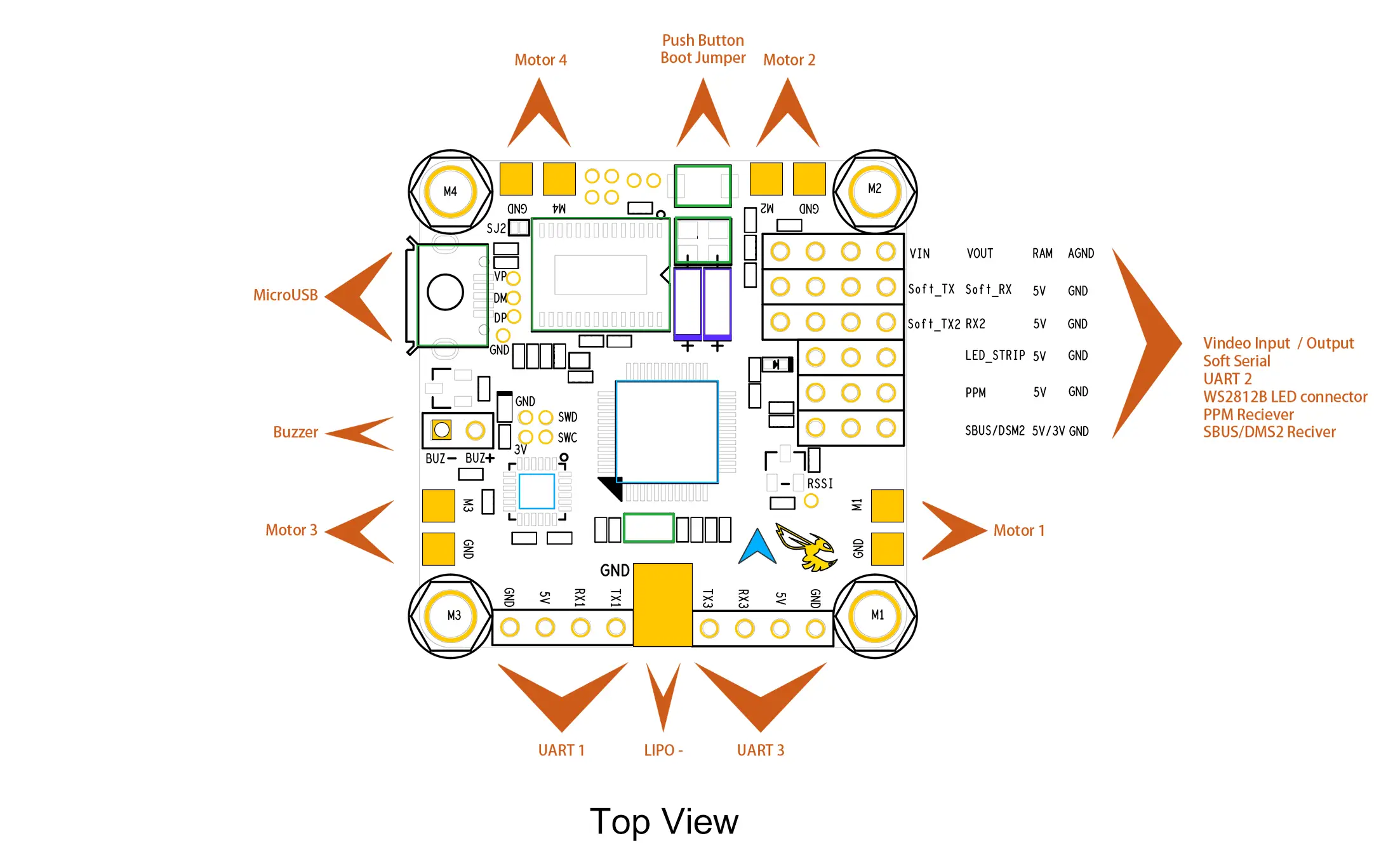
The image below is the top view schematic of the flight controller. What I’m not a huge fan of, though, is that none of the solder pads are labeled on the top side! All the labels are on the bottom(see the image of the top of the FC above), so you have to consult an external diagram such as this one before soldering anything.

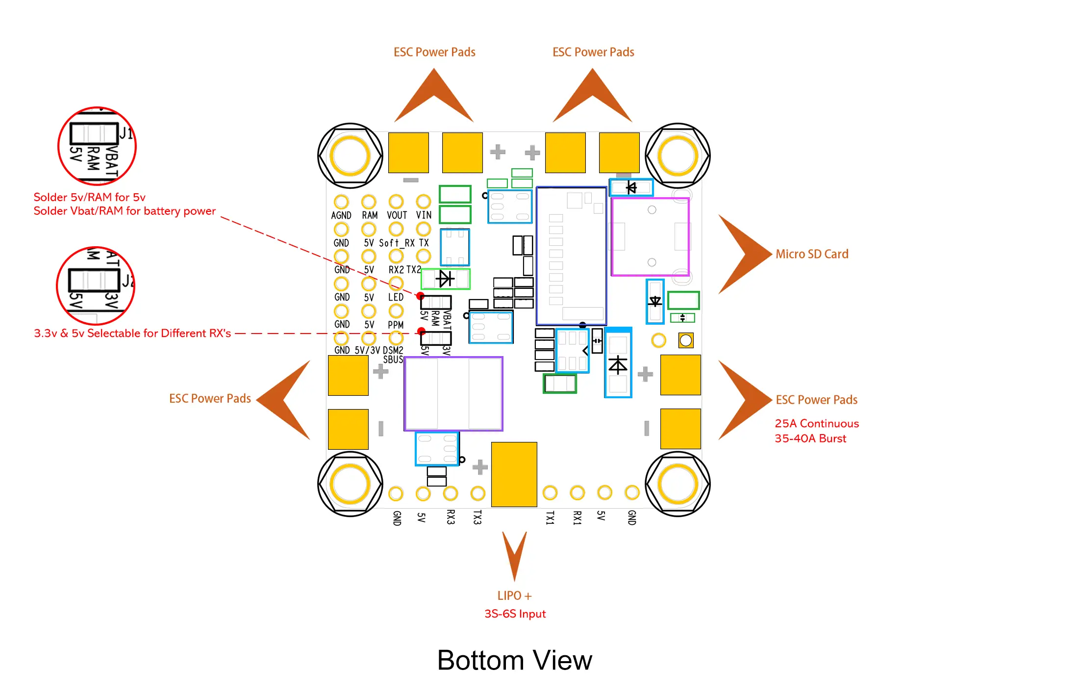
The image below is a bottom view.
As you can see, there’s still a little bit of soldering to do here before you flip the board around to mount properly.
The first row of solder pads(as seen on the left) is AGND, RAM, VOUT, and VIN.
- AGND is filtered ground, which you should use for your Video Transmitter ground. It will help keep the video feed clean and free from disturbances from any voltage spikes
- RAM is positive – whether RAM is raw battery power or 5V can be adjusted by soldering the jumper you can see(zoomed in the red circle) to either RAM 5V or RAM VBAT.
- VOUT is the video out to the video transmitter
- VIN is the video in to the board from the FPV camera
Note: Most new video transmitters and FPV cameras take 2S(8.4V fully charged) to 6S(25.2V fully charged), and won’t work with just 5V, so you’ll need to solder the jumper to RAM/VBAT. The Runcam Split only takes 5V, so take care to jumper the pads to 5V if that’s what you’re using.
The next row is GND, 5V, Soft_RX and TX. Soft_RX and TX is SoftSerial, a telemetry protocol you can enable in your flight controller if your receiver supports it. Older FrSky receivers like the D4R-II had SoftSerial support, but the new SmartPort telemetry on the X4R and XSR is much better.
The next row is GND, 5V, RX2 and TX2. This is UART2 and can be used to hook up any external peripherals like Bluetooth or GPS.
The row below that is GND, 5V, and LED. This is to set up LEDs if you wish – Betaflight lets you configure the colors of the LEDs too.
The next row is the PPM receiver row. If you are using a PPM receiver(though there’s no reason you would want to, serial receivers are now really cheap and faster than PPM).
The last row is for hooking up a serial receiver. You have GND, 5V/3V(which you’ll have to define by soldering the jumper seen in the enlarged red circle), and SBUS/DSM. This is where Spektrum and FrSky SBUS receivers(or FlySky iBUS) go.
If you are using Spektrum receivers, you’ll need to solder the jumper to 3V. If you are using anything else, you’ll solder to 5V.
Note: You MUST solder this jumper for your receiver to get power. If you do not solder it, your receiver will not work!
Soldering the FPV components is rather bothersome
For your FPV gear, you’ll have two components – a camera and a VTx. Both need power, and there is only one pad on the whole section of solder pads that outputs raw battery voltage.
So you’re left with a few options:
- If your video transmitter outputs power(12V), then you can solder just your transmitter power leads to the board and power your camera from the transmitter. Of course, VOUT and VIN need to be connected to the transmitter and camera, respectively.
- If your transmitter does not output power, then you can solder the red positive wire from both the camera and VTx to the same solder pad, and use the same or two different ground pads.
- If you’re using a Runcam Split or any other camera that takes just 5V, that’s the only 5V regulated port that can power the camera, so you’ll need to power your video transmitter(if it only takes 2S-6S) from one of the ESC leads.
- If your transmitter only takes 12V and you’re building a 4S or greater setup, you’ll need to hook up a 12V step down regulator from either the battery pads or the ESC pads and power your transmitter from there.
Betaflight OSD support
All in all, the fact that the board has integrated support for the Betaflight OSD makes life soooooo much easier!
The OSD allows you to see so much vital data on screen, such as battery voltage, current consumed, current draw, flight time, and even PID values.
You can even PID tune by going into the OSD menu – you can also change rates, change PID and rate profiles, and even change the values on the filters!
Final thoughts
The OSD support, and the fact that this is such a clean and low profile build makes this board an excellent choice for any copter. The build quality is solid(you’ll know it when you just hold it in your hand).
However, soldering the board is a little fiddly and frankly is much easier on another OSD enabled board like the Omnibus F4. The Omnibus F4 does not have a PDB built in, though.
I have used the Betaflight board on two of my builds, and in one of them, I could not get the copter to transmit video if the video leads were connected to the board. If they were joined together directly, it would work fine, but when going through the board, nothing.
I searched around and there were other users who had similar issues. FPVModel asked me to send it back to them($20 shipping) or offered 50% off on my next purchase.
Overall, the board is great for a tight, clean build and I recommend it – but it’s far from a perfect board and there is still scope for improvements here and there.
Once you’ve wired up the board, you’ll have to configure it through the Betaflight Configurator, which you can learn more about here.
Leave a Reply
You must be logged in to post a comment.