I’m really excited to share my ZMR 180 mini quadcopter build with you.
Originally, I started out with a ZMR 250, but I wanted to get something smaller, too, which I could fly in tighter spaces. Living in India, there are not as many open spaces to fly, but I do have access to some smaller areas which would be more comfortable to fly in using a smaller quadcopter.
Note: The ZMR250 quadcopter has a diagonal motor to motor distance of 250 mm, and the ZMR180 has a diagonal motor to motor distance of 180 mm – so it’s significantly smaller.
I had ordered an ARF kit a while ago, but my shipment got stuck in customs – perhaps due to the holiday rush – and I finally received it a few days ago.
Unboxing:
Here’s what I got in the box:
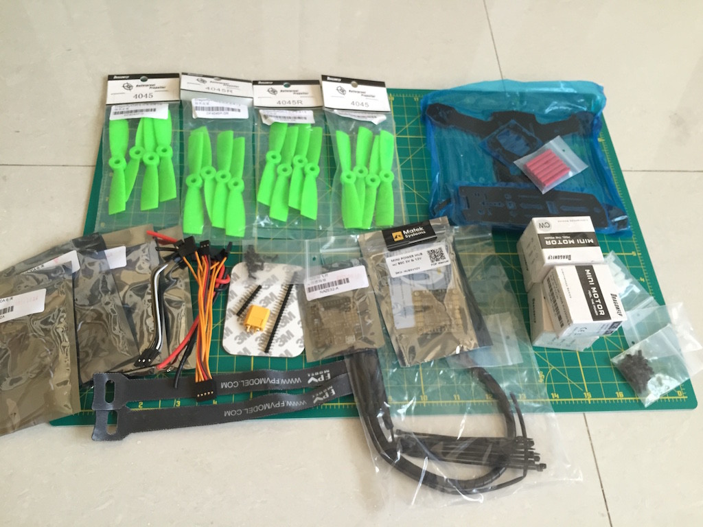
I had ordered the non-FPV kit, since I already had FPV gear. There will be pictures of the FPV gear later in the build.
- ZMR180 Carbon fiber frame: The frame was 3 pieces of carbon fiber and red aluminum standoffs. The bottom plate is 3 mm thick, and the top plate is around 1.5 mm thick. Overall, the frame feels incredibly solid in my hands and very smooth – far better quality than my Banggood ZMR 250.
- Dragonfly 1806/2300 kv motors: These are pretty decent motors – they feel tough in your hand and so far, they are looking good.
- FVT Littlebee 20A ESCs: Littlebee ESCs are awesome because they have the Blheli bootloader and firmware – so you can reverse motor spin through the software, and program all the ESCs through Cleanflight itself(more on that later).
- Matek 5-in-1 PDB: The Matek PDB seems like an awesome option for very small builds. It’s 36 x 36 mm, the same size as most flight controllers. It also has a 12V and 5V output for FPV gear and powering your flight controller, and you can even hook up the FPV video wires to it, making for a very neat build.
- Naze32 Rev 6: The flight controller was the Naze32 Rev6. This is an upgraded Naze32 that has a barometer and 2 MB of onboard flash memory – it’s almost like the older Naze32 full, in fact.
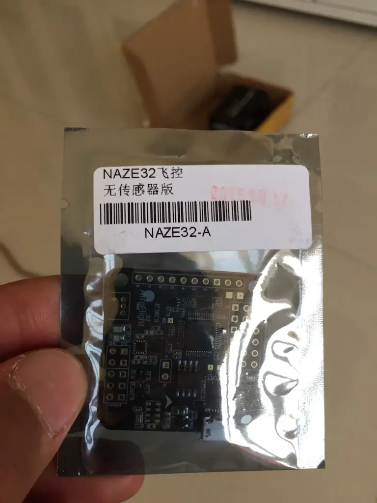
- Dragonfly 4045BN propellers
- Miscellaneous hardware: Battery straps, screws, heat shrink, cable ties, wires, and connectors. This is what I really like about ARF kits – you literally get everything you need, down to the smallest screw. Otherwise it’s usually a trip to the hardware store for the smaller things you found out you didn’t have as you started building!
Other tools you’ll need:
- A soldering iron
- Solder
- Allen keys(hex screwdrivers)
- A hobby knife or blade
- A pair of scissors
- A phillips head screwdriver
- Blue threadlocker(NOT RED!)
- A pair of tweezers would be useful
- Paint markers if you want to decorate the frame
Some more pictures from the unboxing:
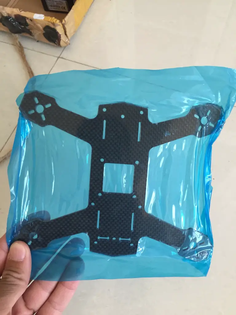
All of the frame parts come sealed in this blue plastic shrink wrap. It’s fun to tear it out!
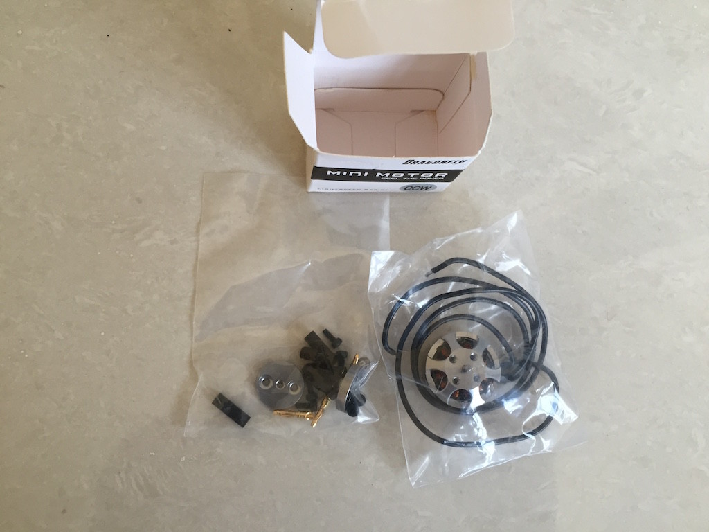
This is what you get with each motor: the motor itself, some bullet connectors(if you choose to use them), the prop shaft, a prop nut, and some screws.
Step 1: The frame
When I took the frame out of the shrink wrap, I saw that some carbon fiber dust was sticking to my hands. Since these frames are machine-cut from sheets of carbon fiber, there’s a little dust left over.
This is not good! Carbon fiber dust is very bad to breathe in, so the first thing I did was wash the frame parts with soapy water(I used dish soap) and laid them out to dry:
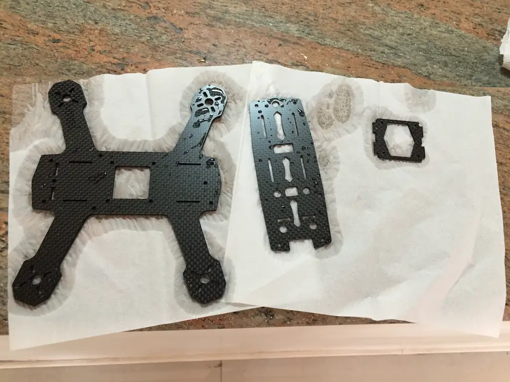
Naturally, I got impatient with the frames drying, so I just took some more tissues and wiped them dry. Since this was my second build, and I had modified my previous build so many times, I was fairly confident about the whole thing, so I decided to bling my quadcopter up a little bit.
I had some Sharpie oil paint markers lying around the house, so I figured I would paint the edges of the frame:
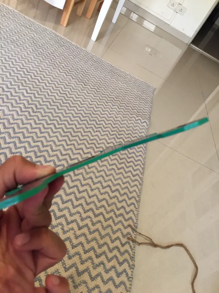
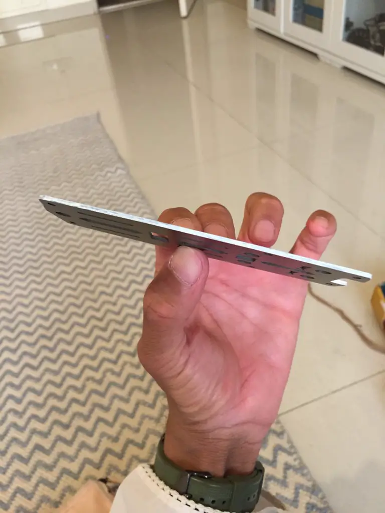
It took a couple of coats to get the color I wanted. I’d run the marker over the edges, wait a couple of minutes for the paint to dry, and then do it again.
Some guys have suggested coating the paint nail varnish so that it won’t come off in crashes. I don’t have any lying around right now, but if I find some, I’ll apply a coating later.
At this point, the frame was ready. Assembling the remaining parts of the frame will be simple, since there’s only 6 standoffs and one FPV mount. I will do that assembly once all of the electronics are in place.
Step 2: The motors
With the frame basically ready, the next thing to do was the motors. As you saw above, each motor came with a prop shaft separate – so you have to screw it in.
I squeezed out some blue threadlocker on the cardboard from the box it came in, and got to work. Screwing the prop shaft in is simple enough. The motor shaft sticks out a little from the top of the motor, so the prop shaft will fit right onto it. Then you just have to align the holes in the prop shaft with the holes in the motor and start putting the screws in.
I dipped the bottom of each screw in the threadlocker and got to work. A short while later, I was done:
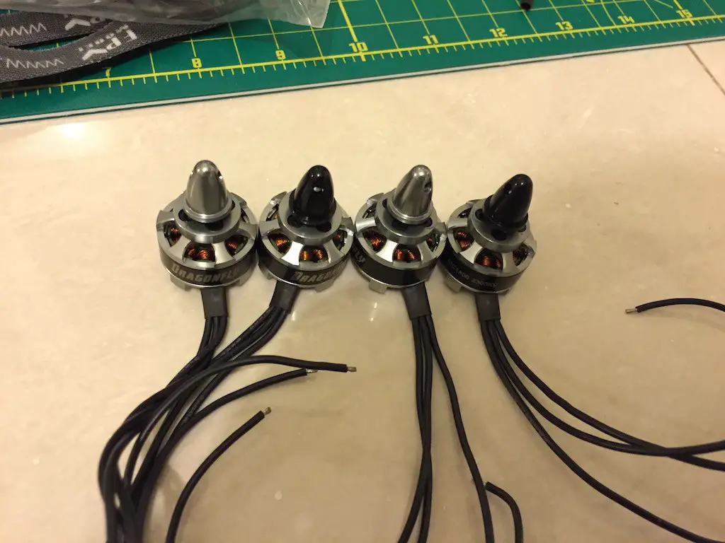
This ZMR 180 ARF kit from FPVModel.com came with two CW and two CCW motors. In this case, CW and CCW does not mean motor direction – it means the direction that the prop shafts are threaded.
So for CW motors, you have to screw on the prop nuts clockwise, and for CCW motors, you have to screw on the prop nuts counter-clockwise.
This is useful because two motors will have to spin clockwise, and two motors will have to spin counter-clockwise – so if you use the opposite threaded motor, so when the motor spins, the prop-nut will not fly off due to vibrations.
Once the motors were prepped and ready, it was time to screw them on to the frame. If you are using the Naze32(or cleanflight on any board), this is how the motors should be spinning:
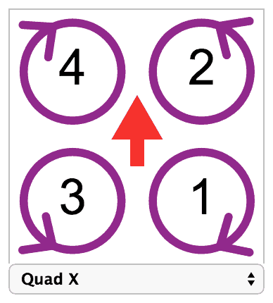
A redditor gave a very good tip for how to check if your motor nuts are threaded properly or not. To make sure your prop nuts won’t spin off, hold the nut still with your finger and spin the motor in the direction it should be going in. If the nut tightens as you spin the motor, you’re good!
Step 3: The ESCs
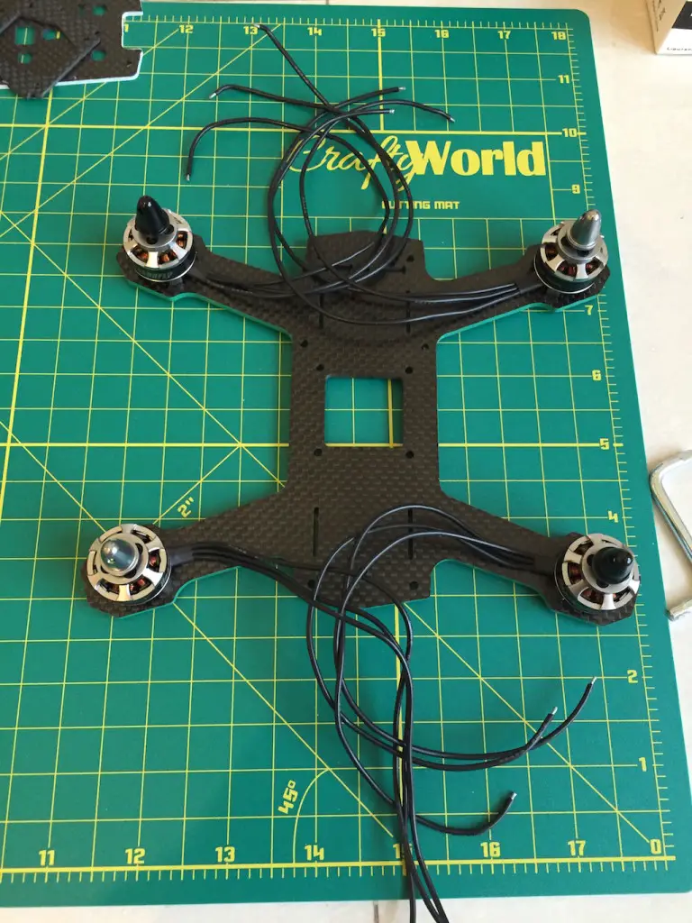
Next up come the ESCs. This build uses FVT Littlebee 20A ESCs, and man, they are tiny! As you can see from the picture above, the motor wires are quite long, so I would have to trim them – but I didn’t want to trim them too short, so I decided to wrap the motor wires from below the ESC, around the back, and directly solder on to the ESC pads.
Note: If you are building for the first time and are not very confident with soldering, I would recommend just splicing the motor and ESC wires instead of what I did.
I had some 16mm heat shrink lying around, so before I tore the heat shrink off my ESCs, I wanted to make sure my new heat shrink would fit! So I cut a piece, put it around the ESC, and shrank it down with a heat gun. It fit!
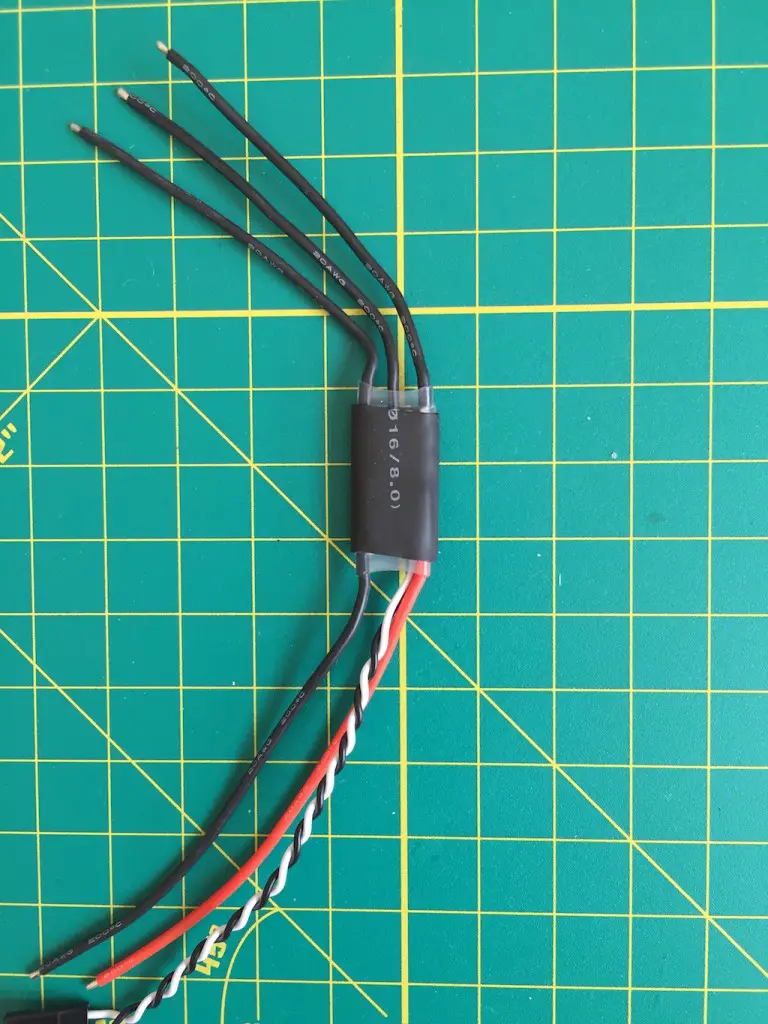
Next up, I cut the heat shrink off all the ESCs and de-soldered the wires that have to be connected to the motors. That’s because I was going to solder the motor wires directly on to the solder pads on the ESCs.
These are the ESCs after prepping:
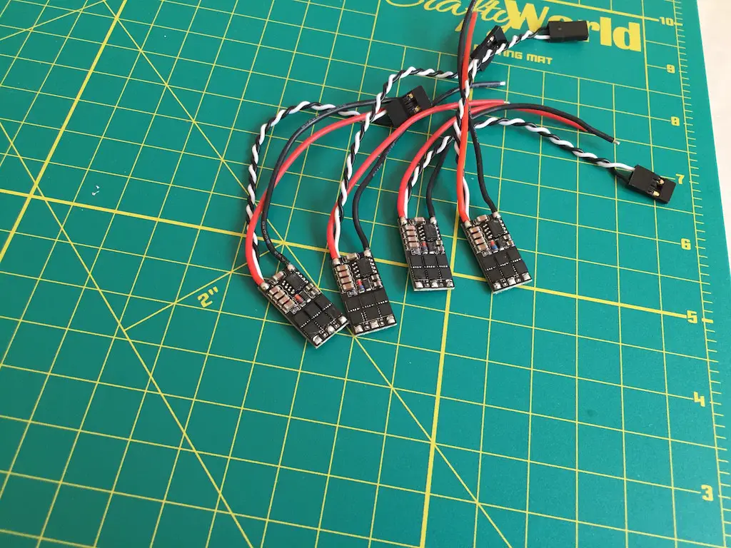
Time to start soldering! I placed the ESC right around where the heat shrink on the motor wires ended, and ran the motor wires below the ESC, then above it and up to the solder pads I had just freed up.
To do that, I bunched the motor wires together and brought them around by bringing them between the positive and negative wires on the ESC – there is a lot of room between those two wires(since the signal wire is closer to the positive wire).
I pinched the motor wires with my fingers to measure length, and cut them down to that size.
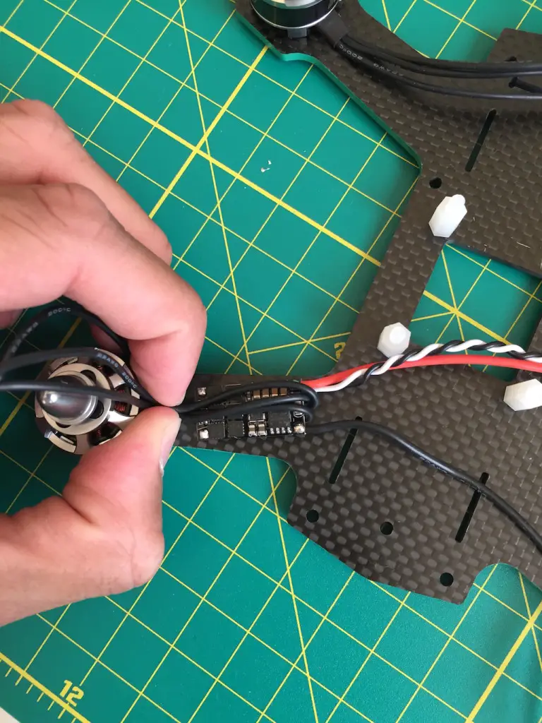
Next step: repeat the process 4 times!
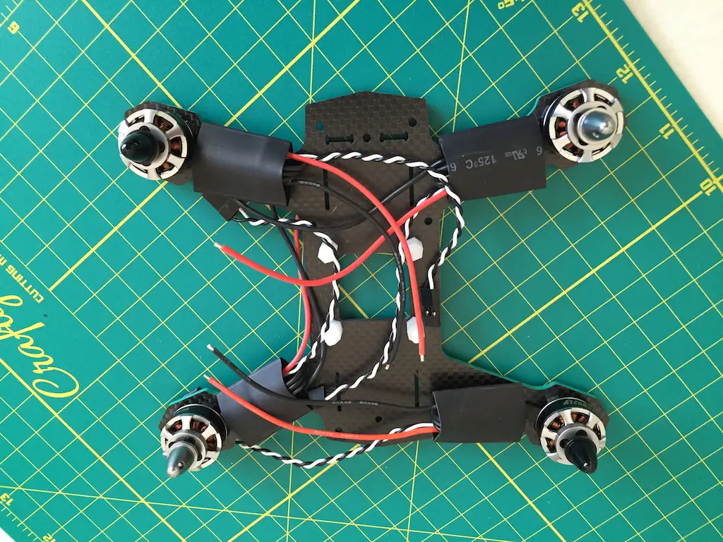
End result(heat shrink ready to be shrunk down):
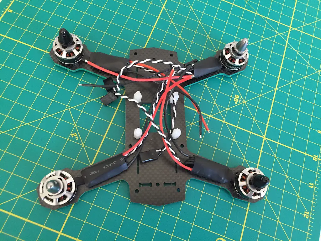
After heat shrink was shrunk down:
Step 4: The Matek 5-in-1 PDB
FPVModel.com sent a Matek 5-in-1 PDB with this kit. I’m super happy with this PDB – it’s just 36 x 36 mm, the same size as the Naze32, and makes the build look really neat.
The Matek board has 4 sets of pads for ESCs, as well as one main battery lead pad and another pad on the other end which outputs the same voltage as the battery.
When you wire in the leads for your battery, make sure to measure and visualize how you’ll connect your battery to the lead once your multirotor is done. You don’t want the wire to be too short, but you also don’t want it to be too long that it gets in the way of the propellers!
I decided to run the wire from directly behind the quad and plug it into the battery direct on the battery.
I used that pad for my VBAT(battery monitoring) that I would connect to the Naze32.
The ESC pads are also position in such a way that you can cut the wires as short as possible and no ESC power wires will overlap.
There is also one dedicated 5V output and one dedicated 12V output. I hooked up the 5V output as my BEC to power the Naze32 board.
Finally, there are two sets of outputs for your video transmitter and camera, which can either be 12V or 5V. The way this works is that you have a positive and ground pad, and next to it, there are a set of bridging pads that say 12V and 5V. If you want to output 12V, you bridge those two pads with solder.
If you want to output 5V, you’ll bridge those two pads.
Both my camera and video transmitter were capable of running on 12V, so I bridged 12V for both. The PDB also had the option of connecting your video signal wires. I did wire it up, but I wasn’t getting a proper video feed, so I removed the video wires from the PDB and just spliced them together directly.
Once I had everything soldered on, I covered up all the open joints with liquid electrical tape.
Step 5: The Naze32 flight controller
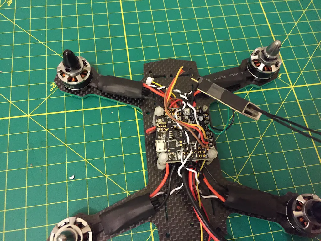
I mounted the Naze32 right above the PDB, spacing them out with nylon spacers that were included in the kit. I think the spacers were 4 mm.
I wanted this build to be as clean as possible, so I direct soldered everything – meaning no signal pins!
There were two sets of wires that would go from the PDB to the Naze32, so to keep the build as clean as possible, I soldered those wires to the bottom of the Naze32 – the solder pads are on both sides.
These two sets were the main voltage which went into the VBAT pins, and the 5V that actually powered the Naze32, which I soldered to the pads for ESC 6 – since I only have 4 motors, ESC 5 and 6 were free.
I also applied liquid electrical tape to the underside where the wires attached, lest they touch the PDB and (gasp) cause a short, and then I screwed on the Naze32 using the nylon nuts provided.
Now it was time to wire up the ESCs to the board!
In the diagram I posted above, the motors are numbered from 1 to 4 – that’s the same order that they must be wired to the Naze32 in.
I took each ESC signal wire and measured it up to the corresponding pad on the Naze32. I added a couple of mm to be safe, and cut the wires at an angle. For example, for two motors, the signal(white) wire would have to reach a little further than the ground(black) wire, and for the other two motors, it would be the other way round.
I soldered the wires in, and the motors were done!
Step 6: The receiver
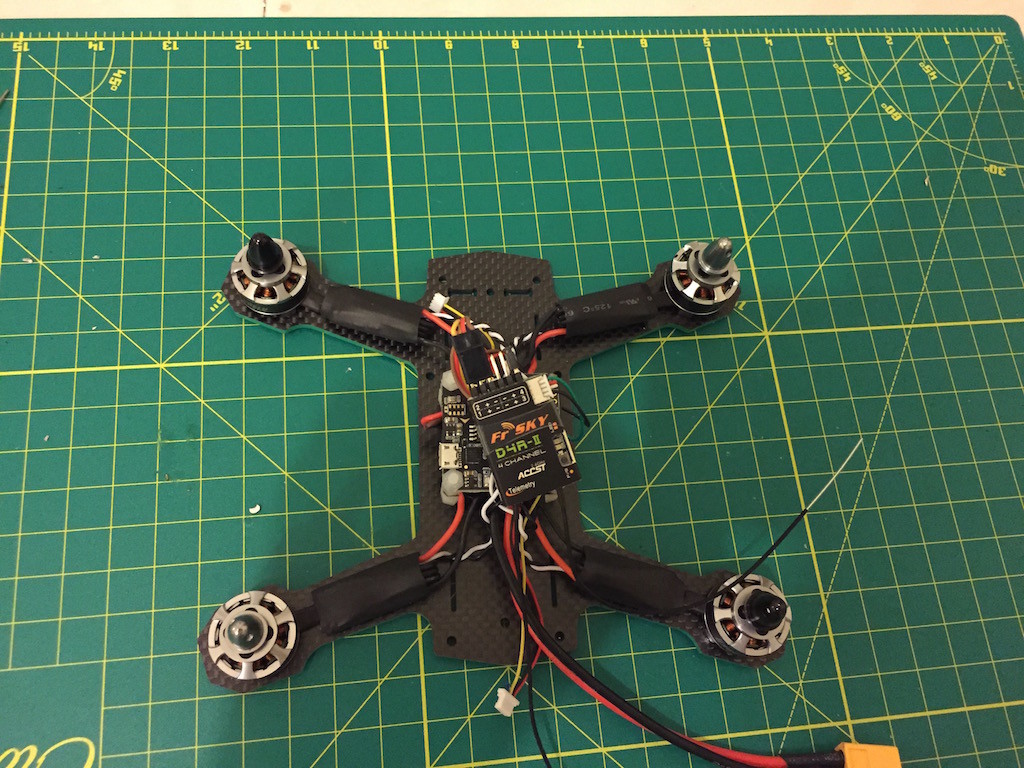
For this build, I used a FrSky D4R-II receiver. This receiver is tiny, supports CPPM(one servo wire for all channels), and telemetry, too. Plus it has awesome range and reliability.
I took a servo wire and cut off the plug from one end.
On the Naze32 rev6, one line is all outputs – the first pad is ground, the second pad is 5V out(to power the receiver), and the third pad is channel one. The next pads are all channels, but since I was using CPPM, I only needed channel one.
I soldered the wire I cut to the corresponding pads, and hooked it up to channel 1 on the receiver. To make sure the D4R-II works in CPPM mode, you have to use the jumper they give you with the receiver and plug it on the pins for channel 3 and 4.
The jumper has a little metal contact inside so what happens is the pins for 3 and 4 are shorted out – now the receiver knows it has to send a CPPM signal.
The D4R-II also has telemetry – these are the wires that plug into the top right of the receiver.
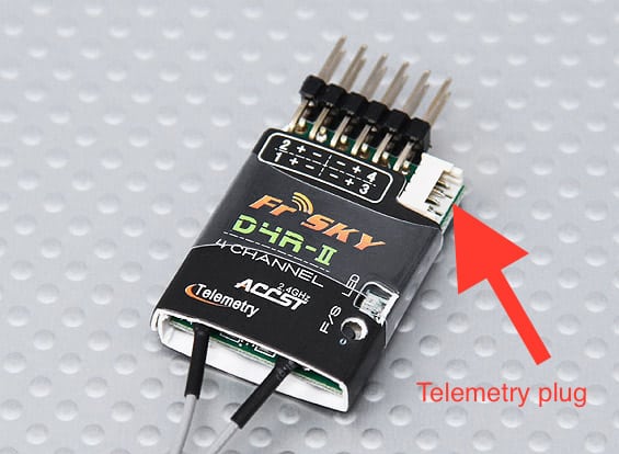
Of these wires, to hook it up with the Naze32, you’ll just need the green(RX) and black(ground) wire. To set up telemetry, I soldered the ground wire directly onto the PDB to any grounding, and I soldered the green wire to receiver pad 6 on the Naze32.
Pad 6 can also be used for Soft Serial, which is a protocol used by the Naze32 and can be used for telemetry. Since my Taranis has the newer firmware, it can’t detect telemetry if it’s from the regular pins, so I use softserial instead.
With all this done, I just had to hook up FPV gear and I’d be finished!
Step 7: FPV Gear
I had already soldered the plugs for the FPV gear onto the PDB, so now I just had to connect the camera and video transmitter and I would be done.
I did hook everything up, and then I connected the battery just to make sure the video signal was coming OK – and also to test the orientation of the camera!
Make sure you know the proper orientation before screwing/attaching the camera!
At first, there was no video signal – all I could see was a black screen! After a little sleuthing, I found out that the camera video signal wire had come loose, so I just soldered it directly to the transmitter video signal wire, removing it from the PDB.
I took some hot glue and stuck the camera on to the camera plate, and screwed the video transmitter to the top plate.
Step 8: Finishing touches
Now that everything was ready, wired up, and tested, it was time to put the finishing touches and complete this build!
I screwed in the standoffs, and began to prepare the top plate.
The top plate has a hole in the back for the transmitters SMA plug(antenna plug) to pop out of – so I passed the transmitter through that, and that was set – it was still a little shaky, so I fixed it in place with a nut.
I also needed some way to run the antenna wires from the D4R-II. I took some zip ties and made two antenna holders at the very back of the plate, since I would need most of the other space for my battery and possible my HD camera!
With the zip ties in place, I took some velcro and attached it to the top of the receiver and the underside of the top plate, and stuck my receiver to the top plate.
Then I screwed the top plate on after making sure everything was in place, and ran the antenna wires along the zip ties and put a length of heat shrink on the antennas and zip ties to hold them together.
The last thing left to do was to have some way that the battery would not slip off. I’ve seen Bruce from RCModelReviews use foam, so I dug up some foam I had, cut a slice, and hot-glued it to the top plate.
Once you strap the battery down on the foam, the foam provides plenty of friction and the battery doesn’t really move after that – so there’s no worry of it flying off mid flight!
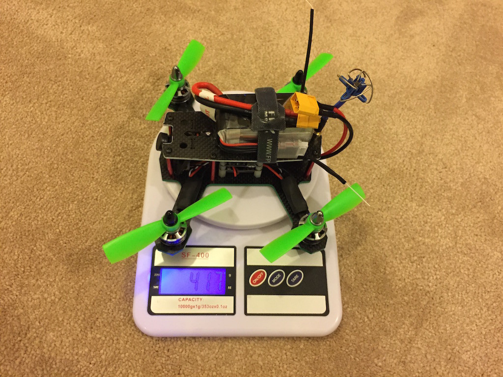
The final weight of the quadcopter including a 4S 1300 mAh battery was around 417 grams. If I wanted to add my Xiaomi Yi, it would be around 490 grams.
Step 9: Final configuration
Since I had hard-wired the ESCs to the motors and all the wires were straight, I had no idea which way the motors were going to turn!
Luckily, these ESCs have the BLHeli bootloader, so I can configure all 4 ESCs at once just by plugging the Naze32 into my computer – how cool is that!
Otherwise, I’d have to use an Arduino tool and flash each ESC individually.
To figure out which motor turned which way, I just had to know which way any one motor turned.
Using the trick from before(pinching the prop nut and spinning the motor), I loosened the prop nut on one motor and pinched it. Then, through BLHeliSuite(the configuration software), I slowly increased the throttle on the motor I was gripping.
If the nut tightened, the motor was spinning the right way. If it spun off, the motor was spinning the wrong way. As it happened, the motor I was testing was spinning the wrong way, so I went into BLHeliSuite and reversed the direction of that motor and the one diagonally opposite.
The quad was finally ready!
All that was left was to make some final changes in CleanFlight and I’d be good to go.
This post has already gotten quite long, so I’ll do another one soon about how to configure Cleanflight.
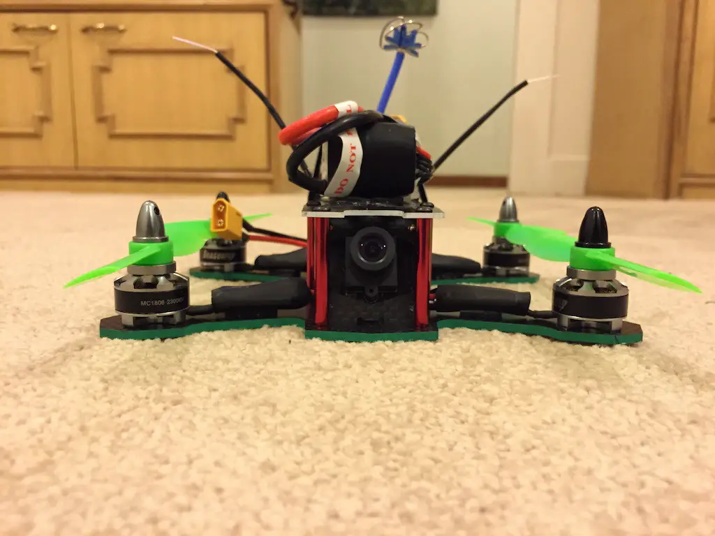
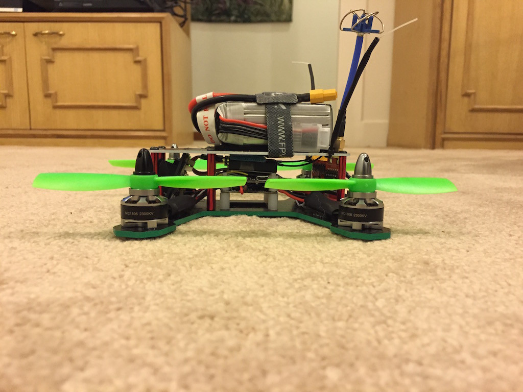
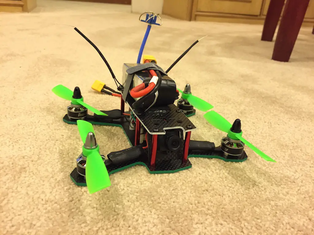
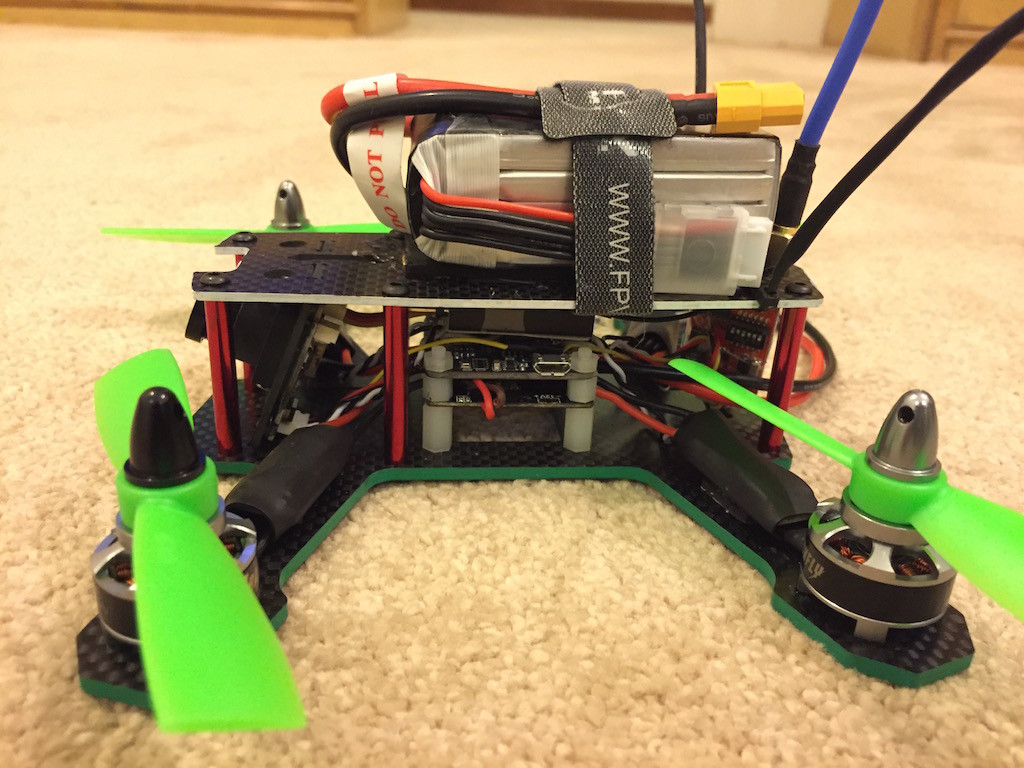
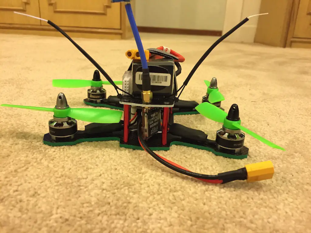
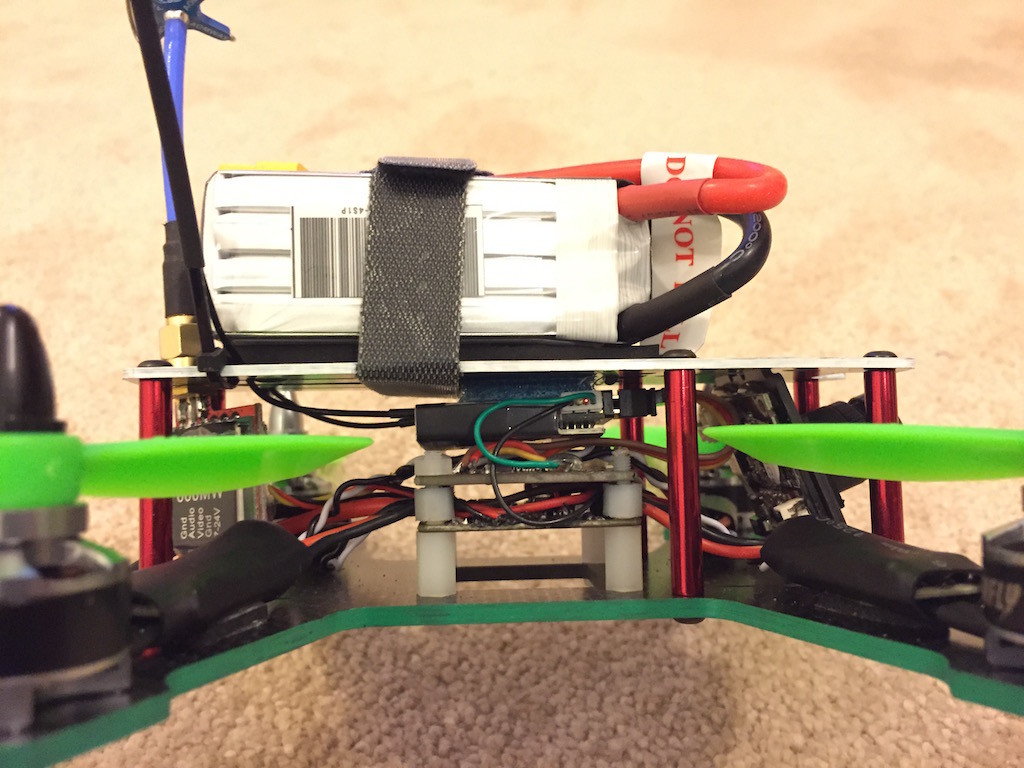
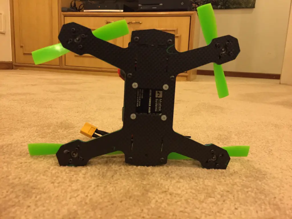
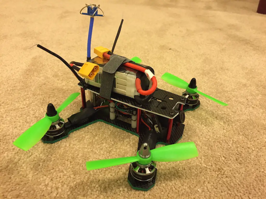
Glamor shots
Hey Gulzaar:
Great article. It has inspired me to take the bold step and build my own instead of getting a store bought. I will send you a message if I get stuck to help me out.
Good Luck!
Hi
I’m Allen from Bonka Co., LTD. if you heared about us and you will know our quality.
Some HOT LiPos list as below:
For FPV Racing :
BK-1300/75-4S (30*34*75mm)
BK-1500/75-4S (28*34*90mm)
BK-1800/75-4S (28*34*107mm)
For RC Helicopter:
BK-850/45-4S (29*30*59mm)
BK-1000/45-4S (22*34*75mm)
BK-2200/45-4S (32*34*107mm)
BK-3300/45-4S (27*43*137mm)
Welcome you send inquiry,thanks!
Best Wishes
Allen
——————————————————————————–
Bonka Co., LTD.
Web:www.bonkapower.com
Email:sales5@bonkapower.com
Skype:bonka-allen
Thanks for walking us through your build. Even though I have just finished my third Mini Quad (2 x ZMR250 and 1 X 5″ Predator) it is always great to see another’s build and how they went about it. Enlightening..